


DeZURIK
BHP High Performance Butterfly Valves
D10503
Page 4
November 2015
Description
The High Performance Butterfly Valve is designed for on-off and throttling applications in the chemical,
power, paper, air conditioning, petroleum and refining industries.
A choice of body styles, ratings, seat and packing options, materials, actuators and accessories are
available in valve sizes from 2–48" (50–1200mm). Pressure and temperature ratings are shown on the
valve data plate.
Handling
Lifting the valve improperly may damage it. Do not fasten lifting devices to the
actuator, disc or through
the seat opening in the body. Lift the valve with
slings, chains or cables fastened around the valve
body, or fastened to bolts or
rods through bolt holes in the flanges.
Installing Valve
Recommendations
Refer to the valve installation drawing for dimensional information.
•
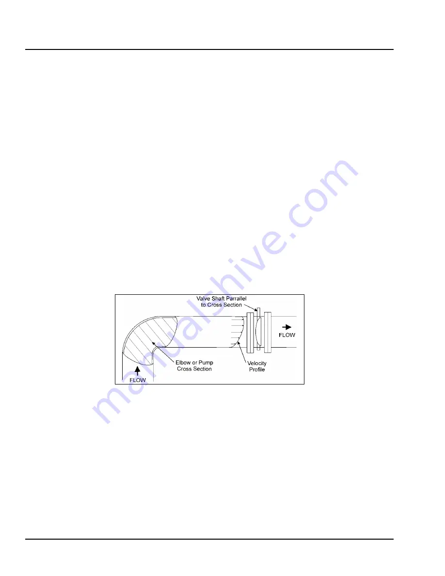
Installing the valve in the wrong location may cause excessive dynamic torque and damage the
valve. When pipeline fluid velocities exceed 20 fps (6.0 m/s) for 12” (300mm) and smaller valves
or 12 fps (3.6 m/s) for 14” (350mm) and larger valves, it is recommended to install the valve at
least 8 diameters from the nearest upstream elbow or pump. For best performance results,
install valve shaft parallel with elbow or pump cross section (see image below). For more
specific installation recommendations, contact your local representative or DeZURIK for
assistance.
•
Valves with undrilled seat retainers are not suitable for dead-end service without a downstream
flange.
•
If possible, install the valve with the shaft horizontal to provide a self-cleaning action on the seat.
Note:
Install the valve so that the side opposite the seat will be on the higher pressure side
when the valve is closed. The seat side of the valve is marked “SEAT”. Pipeline flow may be in
either direction through the valve.
•
Valves with the metal seat option must be installed with higher pressure on the
seat side when the valve is closed.
Use self-centering flat ring flange gaskets.
•
For 2–24" (50–600mm) Class 150 and Class 300 valves, use mating flanges that comply with
the same class of ASME/ANSI B16.5.
•
For larger sizes, use flanges that comply with the Class 150, Series A requirements of ASME
B16.47.