background image

11

www.kronosrobotics.com

Step 8

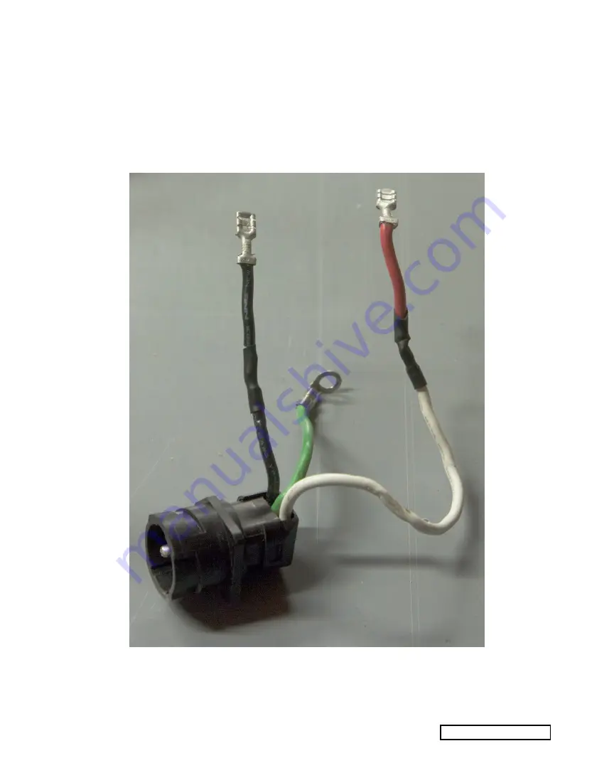
The DW618 router does not have a clamp for attaching a cord, like the other routers do. You could 

still install your own cord using hot glue, I want to show you how to reuse the connector. Cut the black 

wire off the switch and the red wire from the speed controller module.

Solder the red wire to the white wire, and the black wire to the black wire, as shown in Figure 10. 

Be sure to seal the connection with heat shrink or black tape.

Figure 10

Содержание DW618

Страница 1: ...Series Dewalt DW618 Super PID Conversion V2 0 Copyright 2012 Kronos Robotics In this project you will be shown how to convert the Dewalt DW618 router for use with the Super PID Speed controller Please note that this conversion will void your warranty ...

Страница 2: ...nsion cord 25 foot Regulated 5v power supply with hookup wire Super PID Tip You can get a regulated 5v power source a from your PC via the USB cable or from one of the hard drive connectors inside your PC The connector will have four wires Yellow 12V Black GND Black GND Red 5V You will want to use one of the black wires and the red wire The following two links are power supplies that can also be u...

Страница 3: ...m each wire You may want to remove the lock ring from the router This is a requirement of you want to attach an AirExchanger to the router later To remove the ring remove the three screws shown in Figure 1 Once the ring has been removed you need to re attach the screws as they hold the spindle in place Notice that I had to insert two 3 16 washers on each screw You should also download the Super PI...

Страница 4: ...t it best to work on your router after it has been mounted on your CNC This will keep the business end pointed up while you perform the conversion Start by removing the cover To do this remove the four screws then lift the cover off as shown in Figure 2 Figure 2 ...

Страница 5: ...5 www kronosrobotics com Step 2 Using a flat head screwdriver remove the screw shown in Figure 3 Figure 3 ...

Страница 6: ...uter These will all lift out There is a black wire connected to one of the brush mounts There is a red wire connected to the other Pull the connectors off of each mount Every thing should lift out With a small paint brush paint the ring just under the bearing Paint half way around the ring as shown in Figure 4 Figure 4 ...

Страница 7: ...7 www kronosrobotics com Step 4 Shown in Figure 5 is a small platform on the router base next to the bearing Figure 5 ...

Страница 8: ...he plat form using hot glue The goal is to get the sensor as close to the white mark as possible without touching Before gluing refer to the hookup in Step 6 Use the SuperPID to help you get the perfect angle Once you happy with the position glue it in place and hold until the glue is hard Figure 6 ...

Страница 9: ...When the sensor passes over the black portion of the painted band the display should indicate a low reading as shown in Figure 7 When the sensor passes over the white portion of the painted band the display should indicate a high reading as shown in Figure 7 Adjust the sensor as necessary to achieve these readings before preceding to the next step Figure 7 Figure 8 ...

Страница 10: ...cs Dewalt DW618 Super PID Conversion Step 7 Using hot glue to hold the sensor cable in place twist it around as shown in Figure 9 The cable should exit the router at the point where the old switch was located Figure 9 ...

Страница 11: ... install your own cord using hot glue I want to show you how to reuse the connector Cut the black wire off the switch and the red wire from the speed controller module Solder the red wire to the white wire and the black wire to the black wire as shown in Figure 10 Be sure to seal the connection with heat shrink or black tape Figure 10 ...

Страница 12: ...cs Dewalt DW618 Super PID Conversion Step 9 Attach the red and black connectors to the positions shown in Figure 11 Connect the green ground wire back to its original position as shown in Figure 12 Figure 11 Figure 12 ...

Страница 13: ...13 www kronosrobotics com Step 10 Position the power connector as shown in Figure 13 Figure 13 ...

Страница 14: ...14 Kronos Robotics Dewalt DW618 Super PID Conversion Step 11 Slip the cover back in place then insert the four screws and tighten as shown in Figure 14 Figure 14 ...

Страница 15: ...15 www kronosrobotics com Step 12 Attach the original power cable to the router as shown in Figure 15 Figure 15 ...

Страница 16: ...sion Conclusion Attach the power cable to the long end of the cord end with female connector Rout the router up your CNC and around to the dragon cable Figure 16 shows some split flex tubing used to rout the power and sensor cable together Figure 16 ...

Отзывы: