37
EnGLIsH
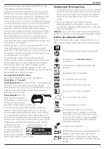
Proper hand position requires one hand on the main handle
3
and one hand on the auxiliary handle
4
.
Instructions for Use
WARNING:
Always observe the safety instructions and
applicable regulations.
WARNING: To reduce the risk of serious personal
injury, turn tool off and disconnect battery pack
before making any adjustments or removing/
installing attachments or accessories.
An accidental
start-up can cause injury.
Switching Pole Hedge Trimmer On and Off
(Fig. A)
Ensure the trimmer head is locked into one of the seven
operating positions. Refer
To
Pivoting the Trimmer
Head
section.
To turn the unit ON, squeeze the lock-off lever
2
and then the
On/Off trigger
1
.
To turn the unit OFF, release the On/Off trigger and the lock-
off lever.
Proper Hand Position (Fig. G)
WARNING:
To reduce the risk of serious personal injury,
ALWAYS
use proper hand position as shown.
WARNING:
To reduce the risk of serious personal
injury,
ALWAYS
hold securely in anticipation of a
sudden reaction.
OPERATION
Instructions for Use
WARNING:
Always observe the safety instructions and
applicable regulations.
WARNING:
To reduce the risk of serious personal
injury, turn tool off and disconnect battery pack
before making any adjustments or removing/
installing attachments or accessories.
An accidental
start-up can cause injury.
Attaching and Adjusting the Shoulder Strap
(Fig. D)
The pole hedge trimmer comes with an adjustable shoulder strap.
1. Snap the shoulder strap latch
17
onto the strap mount
10
located on the unit, just in front of the ON/OFF trigger as
shown. Adjust the strap so it fits over your shoulder.
Joining Trimmer Head Module to Handle
Module (Fig. A, C)
Combining the handle module
15
to the trimmer head
module
21
creates a pole trimmer that is approximately
2.1 m long.
1. Align the groove on the outside of the coupling end of the
handle module
15
with the tongue on the inside of the
coupling end of the trimmer head module
21
.
2. Slide the threaded sleeve
8
on the trimmer head module
down as far as possible and rotate the sleeve clockwise until
it stops and completely covers the threads.
WARNING:
Always check to make sure that the sleeve is
completely threaded on and that the threads are no longer
visible. Not threading the sleeve completely on could
result in the modules becoming disconnected creating a
hazardous condition. Periodically check the connections to
insure that no threads are visible.
Inserting and Removing the Battery Pack
from the Tool (Fig. B)
nOTE:
Make sure your battery pack
6
is fully charged.
To Install the Battery Pack into the Tool Handle
1. Align the battery pack
6
with the rails inside the tool’s
handle (Fig. B).
2. Slide it into the handle until the battery pack is firmly seated
in the tool and ensure that you hear the lock snap into place.
To Remove the Battery Pack from the Tool
1. Press the release button
7
and firmly pull the battery pack
out of the tool handle.
2. Insert battery pack into the charger as described in the
charger section of this manual.
Fuel Gauge Battery Packs (Fig. B)
Some
D
e
WALT
battery packs include a fuel gauge which consists
of three green LED lights that indicate the level of charge
remaining in the battery pack.
To actuate the fuel gauge, press and hold the fuel gauge
button
16
. A combination of the three green LED lights will
illuminate designating the level of charge left. When the level of
charge in the battery is below the usable limit, the fuel gauge
will not illuminate and the battery will need to be recharged.
nOTE:
The fuel gauge is only an indication of the charge left on
the battery pack. It does not indicate tool functionality and is
subject to variation based on product components, temperature
and end-user application.
Pivoting the Trimmer Head (Fig. E–G)
The trimmer head pivots 180° and can be locked into seven
different positions within that range. To avoid being pinched, do
not grab the blades. Wear gloves and hold unit as shown in Fig. G.
WARNING:
Before connecting the battery to the unit, be
sure the trimmer head is locked into position.
To pivot the trimmer head
1. With one hand firmly gripping the trimmer head, use the
other hand to press the lock off button
13
and rotate the
trimmer head handle
14
to pivot the trimmer head.
2. Lock the trimmer head into one of the seven operating
positions as shown in Fig. F. To lock the trimmer head into
place, release your grip on the trimmer head handle
14
.
Check to make sure that trimmer head is locked into
position by trying to move the motor housing. If it is not
locked, rotate it to the nearest lock position.

