


9
English
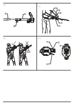
Attaching the Auxiliary Handle (Fig. A, C)
1. Place the auxiliary handle
6
on top of the upper powerhead
pole
19
.
2. Place the handle barrier
17
under the auxiliary handle
6
and
upper powerhead pole
19
so the upper powerhead pole
19
is sandwiched between two handle pieces.
nOTE:
Before assembling further, take care to align the
key
34
on the handle barrier
17
with the key slot
35
on the
underside of the upper powerhead pole
19
.
Inserting and Removing the Battery Pack
from the Tool (Fig. B)
nOTE:
Make sure your battery pack
8
is fully charged.
To Install the Battery Pack into the Tool Handle
1. Align the battery pack
8
with the rails inside the tool’s
handle (Fig. B).
2. Slide it into the handle until the battery pack is firmly seated
in the tool and ensure that you hear the lock snap into place.
To Remove the Battery Pack from the Tool
1. Press the release button
9
and firmly pull the battery pack
out of the tool handle.
2. Insert battery pack into the charger as described in the
charger section of this manual.
Fuel Gauge Battery Packs (Fig. B)
Some
D
e
WALT
battery packs include a fuel gauge which
consists of three green LED lights that indicate the level of
charge remaining in the battery pack.
To actuate the fuel gauge
14
, press and hold the fuel gauge
button. A combination of the three green LED lights will
illuminate designating the level of charge left. When the level
of charge in the battery is below the usable limit, the fuel gauge
will not illuminate and the battery will need to be recharged.
nOTE:
The fuel gauge is only an indication of the charge left on
the battery pack. It does not indicate tool functionality and is
subject to variation based on product components, temperature
and end‑user application.
ASSEMBLY AND ADJUSTMENTS
WARNING: To reduce the risk of serious personal
injury, turn tool off and disconnect battery pack
before making any adjustments or removing/
installing attachments or accessories.
An accidental
start‑up can cause injury.
WARNING:
Use only
D
e
WALT
battery packs and chargers.
•
Young children and the infirm.
This appliance is not
intended for use by young children or infirm persons
without supervision.
• This product is not intended for use by persons (including
children) suffering from diminished physical, sensory or
mental abilities; lack of experience, knowledge or skills
unless they are supervised by a person responsible for their
safety. Children should never be left alone with this product.
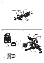
Description (Fig. A, E)
WARNING:
Never modify the area light. Damage or
personal injury could result.
1
Variable speed trigger
2
Lock‑off lever
3
Lock‑off tab
4
Powerhead handle
5
Speed control switch
6
Auxiliary handle
7
Strap mount
8
Shoulder strap (Fig. F)
Intended Use
This powerhead has been designed for powering
D
e
WALT
attachement capable heads. DO NOT use this tool for any job
other than its intended use.
DO nOT
use under wet conditions or in the presence of
flammable liquids or gases.
DO nOT
let children come into contact with the tool.
Supervision is required when inexperienced operators use
this tool.
Date Code Position (Fig. B)
The date code
13
, which also includes
the year of manufacture,
is printed into the housing.
Example:
2020 XX XX
Year and week of Manufacture
Wear ear protection.
No hands
Wear slip‑resistant footwear.
Wear slip‑resistant gloves.
Wear head protection.
Do not expose the tool to rain or high humidity or leave
outdoors while it is raining.
Switch the tool off. Before performing any maintenance
on the tool, remove the battery from the tool.
Keep bystanders away.
Содержание DCMAS5713N
Страница 1: ...DCMAS5713 ...
Страница 3: ...1 Fig A Fig B 14 XXXX XX XX 18 17 Fig C 13 6 9 8 1 6 8 22 9 5 7 3 2 35 19 36 34 ...
Страница 4: ...2 Fig D 5 3 1 Fig F 2 8 7 22 Fig G Fig E 8 19 20 23 6 ...
Страница 36: ...530915 43 RUS UA 01 21 ...


