4
When making a miter cut, the vise (F) may not clamp securely, depending on the thickness of the workpiece and
the miter angle. Other aids (such as spring, bar or C-clamps) will be necessary to secure the workpiece to the
fence when making these cuts.
TO CHANGE SPACING BETWEEN THE FENCE AND VISE
Using the wrench provided, loosen and remove the two fence bolts (Q). Adjust the fence (E) to desired locations.
Insert both fence bolts in provided locations. Securely tighten both fence bolts before use.
Depth Stop (Fig. 1)
Depth stop is set at the factory for a new 355 mm (14") wheel to prevent wheel from cutting into the supporting
surface. To allow more depth of cut, use the 8 mm hex wrench (G) provided to loosen the depth stop bolt (M) and
raise bolt to desired height and then turn jam nut (P) clockwise until seated firmly on the casting. Securely tighten
the depth stop bolt before use.
CAUTION:
When changing to a new wheel, readjust depth stop to original position to prevent cutting into
supporting surface.
Trigger Switch (Fig. 1)
To start the tool, depress the trigger switch (N). To turn the tool off, release the trigger switch. Keep hands and
material from wheel until it has coasted to a stop.
To prevent unauthorized use of tool, install a standard padlock (not included) into the padlock hole (O) located in
the trigger.
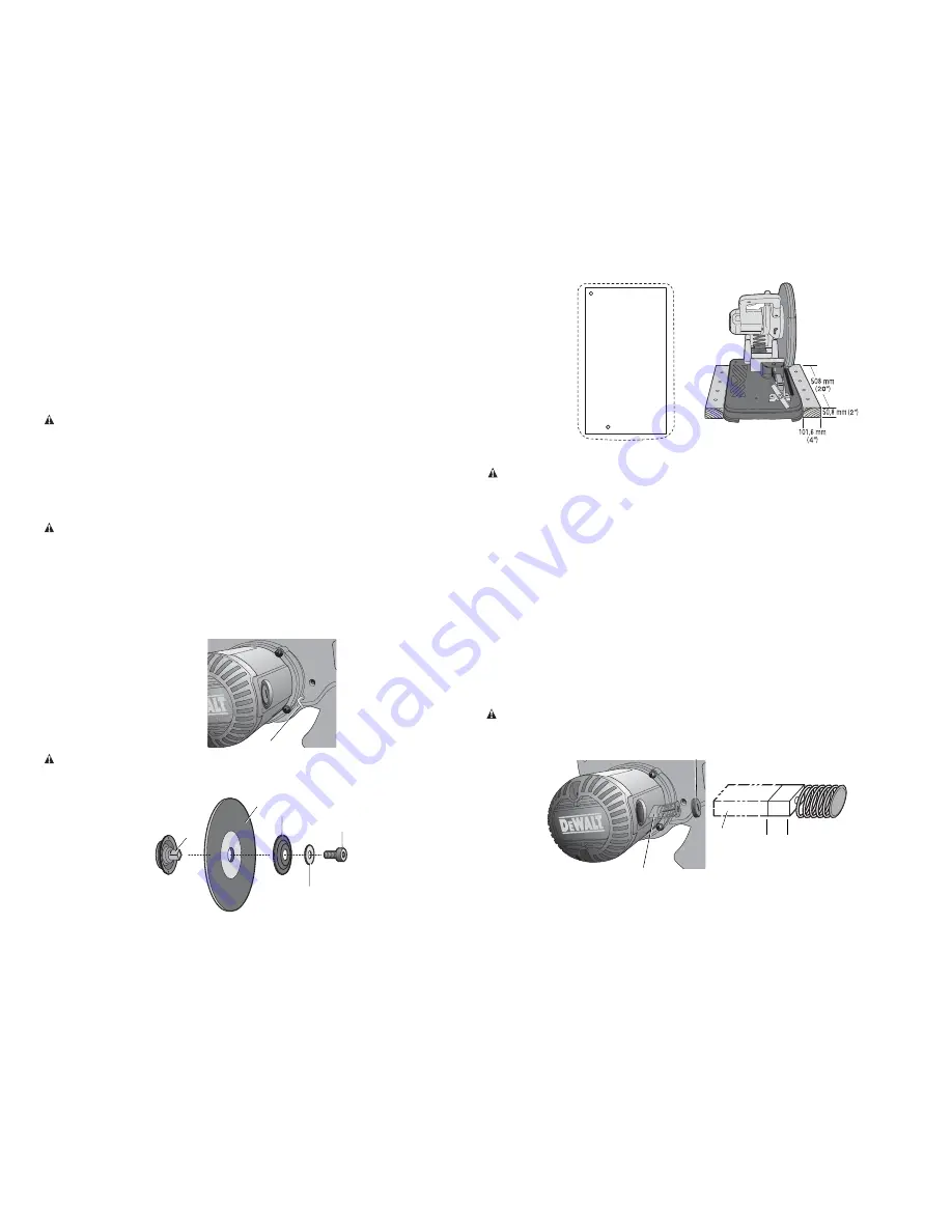
Removal and Installation of Wheels (Fig. 1, 7, 8)
WARNING: To reduce the risk of serious personal injury, turn tool off and disconnect tool from power
source before making any adjustments or removing/installing attachments or accessories. Be sure the trigger
switch is in the OFF position. Do not make any adjustment while the wheel is in motion. Do not make any
adjustment while chop saw is plugged into power supply.
1. Push in wheel lock lever (L) and rotate wheel (J) by hand until wheel lock lever engages slot in inside flange
(S) to lock wheel. Loosen the bolt (T) counterclockwise in the center of the abrasive wheel with the 8 mm hex
wrench (G). Bolt has right-hand thread.
2. Remove the bolt (T), washer (U), outside flange (V) and old wheel (J).
3. Make sure flange surfaces are clean and flat. Install the new abrasive wheel by reversing the above steps.
4. Do not overtighten bolt.
FIG. 7
L
WARNING:
Check the work surface that the chop saw rests on when replacing with a new abrasive wheel. It is
possible that the wheel may contact ANY ITEMS OR STRUCTURE THAT EXTENDS ABOVE work surface (under the
base) when the arm is fully lowered.
S
U
V
J
FIG. 8
T
FIG. 10
FIG. 9
Mounting (Fig. 9, 10)
CAUTION:
Tool must be supported on stable, level, non-skid surface to prevent unexpected movement when
operating.
PROCEDURE FOR PERMANENT MOUNTING
1. Drill two holes 8 mm (5/16") through the work surface (Fig. 9).
2. Insert 1/4–20 screws down through the holes in the base and through holes in mounting surface. The
approximate length of the screws should be the thickness of the mounting surface plus 102 mm (4").
3. Tighten both screws securely.
CRADLE MOUNTING (FIG. 10)
1. Cut two boards approximately 508 x 50.8 x 101.6 mm (20" long x 2" high x 4" wide).
2. Place the chop saw at desired work location.
3. Place boards tightly alongside and nail to work surface.
Operation Tips for More Accurate Cuts
• Allow the wheel to do the cutting. Excessive force will cause the wheel to glaze reducing cutting efficiency
and/or to deflect causing inaccurate cuts.
• Properly adjust fence angle.
• Make sure material is laying flat across base.
• Properly clamp material to avoid movement and vibration.
MAINTENANCE
WARNING: To reduce the risk of serious personal injury, turn tool off and disconnect tool from power
source before making any adjustments or removing/installing attachments or accessories. Be sure the trigger
switch is in the OFF position.
FIG. 11
W
X
6mm
(.2")
X
Motor Brush Inspection and Replacement (Fig. 11)
Brushes should be regularly inspected for wear. To inspect brushes, remove brush cap (W). Brushes (X) should
slide freely in brush box. If brushes are worn down to 6 mm (.2") as shown in Figure 10, they should be replaced.
To reinstall, push new brush back into brush box. If replacing existing brush, maintain same orientation as when
removed. Replace the brush cap (
do not overtighten
).
Содержание D28710-XE
Страница 1: ...D28710 XE HEAVY DUTY 355 mm 14 CHOP SAW INSTRUCTION MANUAL ...
Страница 2: ......


