7
Regular Concrete Installation
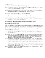
1. Concrete must be level and uniform and have a thickness of 4” with a rating of 3000PSI. The
concrete should be reinforced with wire and rebar.
2. When installing the Blazer 9000 on a concrete floor that has a basement, you should check with
the building architect or manufacturer to determine the proper support for the lift.
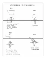
3. Utilize 5/8” anchor bolts when anchoring in regular concrete floors per the above specifications.
Pre-Cast Concrete Installation
1. Pre-cast concrete requires a different anchoring system. Consult with the manufacturer or call for
more information before anchoring the lift on a pre-cast concrete system.
2.
Never use regular 5/8” anchor bolts on a pre-cast floor
.
Other Floor Materials
1. When installing the Blazer 9000 on floor materials other than those mentioned above, consult with
the manufacturer for best type of anchoring system.
Electrical Connection and Power Unit Installation
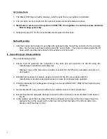
1. The power unit will normally be mounted on the optional power unit stand that also includes the air
valve mounting. Other type mountings, such as pole or wall mounting are possible, but may
require special adapters for the motor mount. The unit owner or manager should approve the
location.
2. If used, the power unit stand will require (four) 3/8” anchor bolts which are provided with the stand.
3. 230-Volt Electrical Operation: The power unit comes wired and ready to plug into a 230-volt, single
phase, 60 Hz circuit. Use dedicated, single phase, 2
5
-
AMP
breaker with time delay fuse or
circuit breaker. Wiring must comply with local electrical codes.
Hydraulic Connections
1. Reference the hydraulic diagram for instructions on connecting the hydraulic hose on the Blazer
9000. The lift comes standard with small connector hoses that can be used with any length
hose depending on how far the power unit is mounted from the lift. The standard length
hydraulic hose supplied with the unit is
1 @
2
6' and 1 @ 14'
. Additional hose lengths can be
purchased as required. The hose length does not have to be the same as long as the air is
properly bled
from the system during installation. See page 13 for further instructions.
2. The power unit operates at high pressure and adequate care must be taken to make sure all hose
fittings are securely tightened. Severe leaking will occur if the hose fittings are not properly
tightened.
3. The power unit requires
7-1/2 - 8
quarts of Dexron III Automatic Transmission Fluid or an equivalent.
4. Make sure breather cap is functional and not broken.
Содержание BLAZER 9000
Страница 4: ...4 Layout Dimensions...
Страница 5: ...5 Layout Dimensions...
Страница 6: ...6...
Страница 14: ...13 921 8 17 5 48 30 17 PARTS MANUAL BLAZER 9000...
Страница 15: ...14...
Страница 17: ...16...
Страница 19: ......


