Devilink eCentral-1208 Скачать руководство пользователя страница 1

2

devilink™ System Overview 

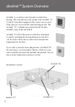
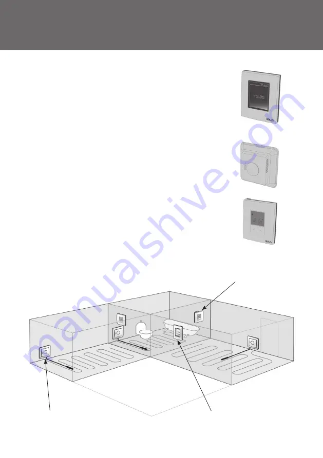
devilink™ is a wireless control system for underfl oor 

heating. Th e central brain in the system is the devilink™ CC 

(Central Controller) equipped with a colour touch screen. 

From this you can control the entire heating system. Th e 

devilink™ CC communicates wirelessly with all other 

devilink™ units in the installation.

devilink™ FT (Floor Th ermostat) is fi tted in individual 

rooms for switching the heating element on and off . It 

can also have a fl oor sensor connected to measure the 

temperature in the fl oor.

If you wish to measure room temperature, a devilink™ RS 

(Room Sensor) can be installed. Th is has a built-in room 

sensor and thus measures the ambient temperature. You can 

also turn the temperature up/down via this.

Installation scenario:

devilink™ RS

devilink™


FT

devilink™


CC

Содержание eCentral-1208

Страница 1: ...other devilink units in the installation devilink FT Floor Thermostat is fitted in individual rooms for switching the heating element on and off It can also have a floor sensor connected to measure t...

Страница 2: ...ically be between 140 170 cm In wet rooms it should be installed on an even surface according to local building regulations At least 50 cm away from windows doors that will occasionally be left open N...

Страница 3: ...ing to the connection diagram on the back of unit Mount the PSU with the 4 screws Mounting devilink CC with NSU Hold the mounting plate on the wall and mark up the 4 screw holes Make sure the top is l...

Страница 4: ...an installer tool a Slide the lid off and insert 10 new unused AA alkaline batteries into the BSU Ensure that the batteries are in the correct position Slide the lid back on and attach the Battery Pac...

Страница 5: ...select your choices c Remove the front cover from the CC by gently pulling it off Press and hold the install pin with a pen for 3 seconds to start the installer menu If you are in doubt you can alway...

Страница 6: ...7 d Now create the rooms where the local units are installed Add New Room The Configure Room menu now appears Press Room Devices and then Add a Device 3 Configuration of devilink...

Страница 7: ...view of the devices associated to the room Max 1 5 m 3 Configuration of devilink devilink automatically selects the regulation principle according to the types of devices in the room If you want to ch...

Страница 8: ...f the battery pack and place the devilink CC on the mounting plate that you installed earlier It will now power up again and show you a screen like this Press select the install pin again to finalise...

Страница 9: ...t is waiting for the devilink RS units You have to go to all the devilink RS units only and press the ON OFF button for 5 sec 3 Configuration of devilink e Network test When installation is complete o...

Страница 10: ...an outdoor sensor Go to section 4 2 d Changing parameters for Heating Control Go to section 4 3 4 1 Adding a device s to an existing room On the Service menu go to Room and Devices and press Configure...

Страница 11: ...12 4 2 Adding a service device A service device is for instance an outdoor sensor tariff module power meter etc You should do a network test now See section 3 e 4 Modifying an existing Installation...

Страница 12: ...ature in living rooms etc Install the Floor sensor and a devilink RS Choose Combined regulationwhen doing the configuration on the devilink CC No floor sensor A floor sensor is not present and cannot...

Страница 13: ...4 Modifying an existing Installation To change the type of regulation go to the service menu 14...

Страница 14: ...ill need to enter the pin code 0044 Notice The floor temperature is measured where the sensor is placed The temperature at the floor sensor can differ a number of degrees from that measured on the top...

Страница 15: ...device to be removed To add a replacement device just follow process described in 4 1 Adding a device 4 4 Removing or Resetting a device You can remove any local device from your devilink system by re...

Страница 16: ...Trouble shooting 5 1 Warnings If an alert or warning occurs a yellow alert icon will be shown on the Standby screen Now press the red button and then the View Alerts to find more infor mation on the i...

Страница 17: ...system once again Add Device Q why can t I add a FT to a room A If a FT is already included in a room the sensor configuration on the additional FT s must be the same There is a maximum of 4 FT s per...

Страница 18: ...ttery level Critical on device Battery level low on device Device not responding Too many dead devices Heating turned off in a room Min floor temperature limit Tamper proof Restrictions enabled Manual...

Страница 19: ...a chain 3 Transmission power Max 1 mW IP class 21 Dimensions 125 mm x 107 mm x 25 mm devilink PSU In Wall Operation Voltage 100 250 VAC 50 60Hz Output Voltage 15 VDC 10 Standby power consumption Max...

Отзывы: