


30.1.20
Instruction manual dynamic switching accelerator SPEEDY V. 3.1
17
Deutschmann Automation GmbH & Co. KG
SPEEDY switching modes
5.6
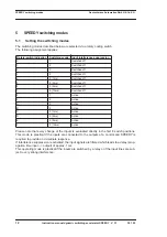
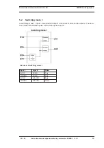
Switching mode 5
Switching mode 5 also includes an RS flip-flop which is set via inputs 1 and 2 and reset via inputs
3 and 4 (cf. description in switching mode 4). The pulse length is set via the rotary coding switch,
with the following assignment:
Picture 6:
Switching mode 5
Rotary switch indication
Pulse
1ms
2ms
6 or E (see chapter 5.1)
5ms
7 or F (see chapter 5.1)
10ms
Input 1
Input 2
Input 3
Input 4
Output 1
Output 2
0 VDC
0 VDC
0 VDC
0 VDC
Unchanged
Unchanged
+24 VDC
0 VDC
0 VDC
0 VDC
Unchanged
Unchanged
0 VDC
+24 VDC
0 VDC
0 VDC
Unchanged
Unchanged
+24 VDC
+24 VDC
0 VDC
0 VDC
+UB
0 VDC
0 VDC
0 VDC
+24 VDC
0 VDC
0 VDC
+UB
+24 VDC
0 VDC
+24 VDC
0 VDC
0 VDC
+UB
0 VDC
+24 VDC
+24 VDC
0 VDC
0 VDC
+UB
+24 VDC
+24 VDC
+24 VDC
0 VDC
0 VDC
+UB
0 VDC
0 VDC
0 VDC
+24 VDC
Unchanged
Unchanged
+24 VDC
0 VDC
0 VDC
+24 VDC
Unchanged
Unchanged
0 VDC
+24 VDC
0 VDC
+24 VDC
Unchanged
Unchanged
+24 VDC
+24 VDC
0 VDC
+24 VDC
+UB
0 VDC
0 VDC
0 VDC
+24 VDC
+24 VDC
Unchanged
Unchanged
+24 VDC
0 VDC
+24 VDC
+24 VDC
Unchanged
Unchanged
0 VDC
+24 VDC
+24 VDC
+24 VDC
Unchanged
Unchanged
+24 VDC
+24 VDC
+24 VDC
+24 VDC
+UB
0 VDC
Содержание SPEEDY Series
Страница 2: ...Handbuch Art Nr V3140E...
Страница 22: ......


