Instruction Manual
for
DEUBLIN
Bore-Mounted
Two-Channel Rotating Unions
Model/Series:
1112-240-001
Number:
Release: 275 V
Page 6 of 11
DEUBLIN Company • 2050 Norman Drive • Waukegan IL 60085-6747 USA • +1-847-689-8600 •
+1-847-689-8690 •
Installation Procedure
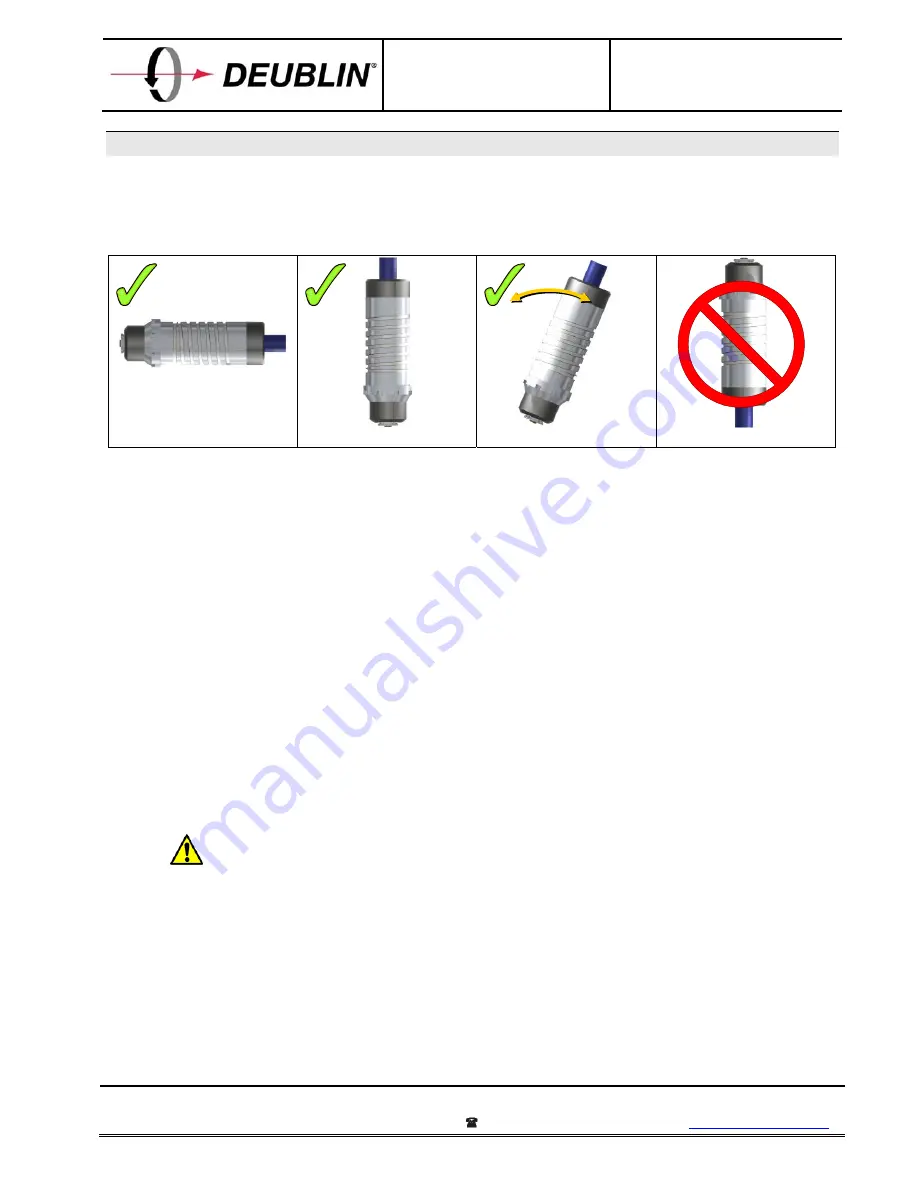
1112-240-001 is suitable for horizontal, vertical, or yoked spindle (B-axis) applications. In vertical
applications, the rotating union should be installed with the rotor pointed down. Although the union will
operate with rotor pointed up, in this orientation the union is more easily affected by media contamination and
incorrect drain hose position. Therefore, this orientation is
not
recommended.
Horizontal spindle
Vertical spindle
Yoked (B-axis) spindle
Vertical spindle pointed up
A
DEUBLIN
rotating union is a highly engineering piece of equipment, containing precision bearings and
many small parts. Dropping the union, using it as a hammer, or applying excessive external forces can cause
internal damage and shorten the union’s operating life.
To install the
DEUBLIN
1112-240-001 rotating union, follow these steps:
1.
Measure runout near the end of the drawbar extension, using hand rotation of the spindle and a dial
indicator. If runout exceeds 0.050 mm, then adjust the drawbar extension to minimize runout.
2.
Make sure that shaft seals in union are clean. GENTLY remove any visible contaminants, then
lubricate both shaft seals in the union rotor with O-ring grease.
3.
Make sure drawbar extension is clean. Lubricate sliding diameter of the drawbar extension with O-
ring grease.
4.
Make sure end of lance is free of debris and contaminants. Lubricate the lance O-ring with O-ring
grease.
5a.
Remove the 1/8” PTF flush plug that is pre-installed into a flat surface of the union. Rotate the
union rotor until one of the two M3 set screws is visible. Loosen set screw completely, then
engage the threads and turn clockwise NO MORE than two full turns.
If set screw is turned more than 2 full turns after thread engagement, the lance O-ring may
be damaged during lance insertion. A damaged lance O-ring can allow coolant to leak into
the air channel.
5b.
Rotate the union rotor 180° until the other M3 set screw is visible. Loosen set screw completely,
then engage the threads and turn clockwise no more than 2 full turns.
6.
Insert lance into union rotor approximately 88 mm (3.5”), until it can slide no further. Be sure to
keep the lance centered in the union rotor during insertion.
7.
GENTLY tighten one of the M3 set screws approximately one full turn, until it just touches the
lance. Do NOT tighten set screw completely. Rotate the union rotor 180° and repeat this for the
other M3 set screw.


