


DDEC V TESTING
VPOD Wiring Test
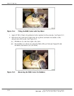
Perform the following steps to test the VPOD wiring.
NOTE:
VPOD power should have been veri
fi
ed during the VPOD and Supply Voltage Test and
Part Number Check. If not, perform a VPOD Part Number and Supply Voltage Test.
1. Turn ignition switch ON.
2. Disconnect the VPOD sensor connectors.
3. Insert a 1,000
resistor between cavities Number 2 and Number 1 for a 12 V version,
or cavities Number 2 and Number 3 for a 24 V version.
4. Connect a VOM to the VPOD connector between pin Number 2 and pin Number 3 for a
12 V VPOD or pin Number 2 and pin Number 1 for a 24 V VPOD.
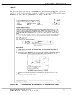
5. Using either a DDDL or DDR, activate the PWM #4 (VNT) and ensure that activating 50
% duty cycle: VDC = 50% of the VPOD supply voltage ± 1 volt. (e.g. voltage to VPOD =
13.8 V * 0.5 = 6.8 V, therefore 5.8 V to 7.8 V at VPOD is okay).
6. Listen for air leaks from the VPOD when PWM are activated to 50%.
[a] If the PWM voltage measurement is correct, go to step 7.
[b] If the PWM voltage measurement is incorrect and the wiring checks were correct, try
a test ECU programmed for EGR or contact the Detroit Diesel Customer Support
Center at 313-592-5800.
7. Verify repairs. Perform an Active Codes Test.
10-18
All information subject to change without notice.
(Rev. June 2005)
7SE60 0506
Copyright © 2005 DETROIT DIESEL CORPORATION
Содержание Series 60 EGR
Страница 1: ......
Страница 171: ......
Страница 172: ......
Страница 173: ......
Страница 174: ......
Страница 177: ......
Страница 179: ......
Страница 180: ......
Страница 181: ......
Страница 182: ......
Страница 183: ......
Страница 184: ......
Страница 185: ......
Страница 186: ......
Страница 187: ......
Страница 188: ......
Страница 189: ......


