


7
Installation Guide
M100-ADSL Interface DSL Modem
LED 2 indicates that there is a connec-
tion between the switch on the expan-
sion module and the modem (the LED
is illuminated continuously). LED 2 is
temporarily extinguished when LED 5
flickers, i.e. during a data transfer via
Ethernet.
LED 3 is off when the modem is down.
LED 3 flashes on and off in 250-ms cy-
cles when the modem is in active. After
approx. 2.25 seconds, the modem goes
from the active state to the “down”
state for approx. one second. In the
“showtime” state (= synchronised),
LED 3 is illuminated continuously.
LED 4 is off as long as there is no data
transfer via ADSL. During data transfer
via ADSL, LED 4 flickers at a speed de-
pending on the data transfer rate.
LED 5 is off as long as there is no data
transfer via Ethernet. During data
transfer via Ethernet, LED 5 flickers (in
this case, LED 2 is off).
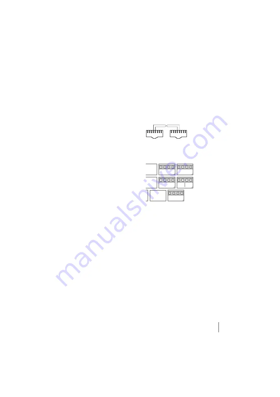
Pin outs
As an alternative to using the RJ45
sockets to connect the interface card to
the splitter, you can use the pressure
terminals (slot no. 3).
The RJ45 cable pin outs
Connection of an interface card to
pressure terminals
Configuration
When you have restarted the
OpenCom 130, you use the
Configurator
in the Web console to
configure the DSL modem. Please also
refer to the information in the
OpenCom 130 online help.
Proceed as follows:
1. Log in to the
Configurator
as a
user with administrator rights.
Note:
In order to configure the DSL
modem via the OpenCom 130 Web con-
sole, you require Version 5.1 or higher of
the firmware. If necessary, first use the
SYS Configuration: Firmware
menu to
load the new firmware. Then use the
SYS Configuration: Components
DSL Splitter
Pin 4: U-R2 a
Pin 5: U-R2 b
1 2 3 4 5 6 7 8
1 2 3 4 5 6 7 8
DSL Modem
Slot 3
a
U-R2
b


