Despatch MIC 1162 Скачать руководство пользователя страница 45

41

APPENDIX B: HARDWARE DEFINITION CODE

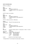
The Hardware Definition Code is used to represent the hardware installed (input type,
Output 2 type and Output 3 type); this must be compatible with the hardware actually
installed.  It can be accessed, with the instrument in Configuration mode, by
simultaneously depressing the DOWN and SCROLL keys.  The displays will show

XXXX

 (where X represents any number) in the upper display and 

dEFn

 in the lower

display, where:

the first (left-most) digit is input type:

1 =RTD/Linear mV
2=Thermocouple
3=Linear DC mA
4=Linear DC V

the second digit is Output 1 type:

1=Relay

the third digit is Output 2 type:

0=Output 2 not installed
1 =Relay (Alarm Only)

the fourth digit is Output 3 type:

O=Output 3 not installed
1 =Relay (Alarm 1 only)
2=SSR (not available)
3=DC 0-10V (retransmit only)
4=DC 0-20mA (retransmit only)
5=DC 0-5V (retransmit only)
7=DC 4-2OmA (retransmit only)

The displayed code may be incremented/decremented using the UP/ DOWN keys as
required.  The maximum setting available is 4117.  For example, the code for a
thermocouple input, Relay Output 1 and Relay Output 3 would be 2101.  When the
code is first altered, the code display will flash, until the desired value is displayed and
confirmed by pressing the Reset key.

Содержание MIC 1162

Страница 1: ...REV 4 99 E 89 P N 136107 MIC 1162 1 16 DIN HIGH LOW LIMIT CONTROLLER REFERENCE MANUAL Copyright 1999 by Despatch Industries...

Страница 2: ......

Страница 3: ...ut Connections 13 SECTION 3 OPERATION 15 3 1 Power Up Procedure 15 3 2 Keypad Operation 15 3 3 Displays 16 3 3 1 Alarm Status Display 16 3 3 2 Over Range Under Range Display 16 3 4 Front Panel Indicat...

Страница 4: ...ii...

Страница 5: ...er thermocouple RTD mVDC VDC or mADC inputs The instrument can operate from either a 90 264 VAC 50 60 HZ power supply or optional 24V AC DC power supply 1 2 Displays Each instrument is provided with d...

Страница 6: ...s and Indicators 1 4 Process Variable Setpoint Value Retransmission Output If the instrument is specified with this option this output may be scaled over any desired range and re transmitted through o...

Страница 7: ...ly orientated A stop will operate if an attempt is made to insert the instrument incorrectly Recommended panel opening sizes are illustrated in Figure 2 1 After the opening is properly cut insert the...

Страница 8: ...4 FIGURE 2 1 Panel Cut Out Dimensions FIGURE 2 2 Main Dimensions...

Страница 9: ...must be followed to minimize the effect of noise upon any instrumentation 2 2 1 Installation Considerations Listed below are some of the common sources of electrical noise in the industrial environme...

Страница 10: ...voltmeter check between neutral and ground should be done On the AC range the reading should not be more than 50 millivolts If it is greater than this amount the secondary of this AC transformer supp...

Страница 11: ...r transducer 2 2 5 Noise Suppression At The Source Usually when good wiring practices are followed no further noise protection is necessary Sometimes in severe electrical environments the amount of no...

Страница 12: ...ical noise as well as damage to the contacts Connecting a RC network properly sized can eliminate this arc For circuits up to 3 amps a combination of a 47 ohm resistor and 0 1 microfarad capacitor 1 0...

Страница 13: ...n 10 feet If the temperature probe is to be subjected to corrosive or abrasive conditions it should be protected by the appropriate thermowell The probe should be positioned to reflect true process te...

Страница 14: ...ent will operate on 90 264V AC 50 6OHz main supply The power consumption is approximately 4 VA Connect the line voltage hot and neutral to terminals 9 to 10 respectively as illustrated below FIGURE 2...

Страница 15: ...st be positioned correctly see Appendix A and Hardware Definition Code must be correct see Appendix B FIGURE 2 10 Volt mV Input Make volt and millivolt connections as shown below Terminal 5 is positiv...

Страница 16: ...12 FIGURE 2 11 Remote Digital Communications RS485 Make digital communication connections as illustrated below FIGURE 2 12 Remote Reset Connections are made as illustrated below for remote reset...

Страница 17: ...resistive 120 240 VAC FIGURE 2 14 Relay Output 2 Alarm or Annunciator Connections are made to Output 2 relay as illustrated below The contacts are rated at 2 amp resistive 120 240 VAC FIGURE 2 15 Rela...

Страница 18: ...14 FIGURE 2 16 mADC Output 3 Recorder Output Only Make connections for DC output 3 as illustrated below...

Страница 19: ...condition after the process is within the limit 2 Acknowledge that the limit has been exceeded 3 Confirm entry in Configuration Mode SCROLL KEY This key is used to 1 Select a parameter to be viewed or...

Страница 20: ...can be altered by the Display parameter in the Setup mode 3 3 1 Alarm Status Display The user may view the status of the instrument s alarm s by depressing the SCROLL key until the lower display shows...

Страница 21: ...is not pressed The indicator is on steady if the error has been acknowledged i e Reset key has been pressed Note This LED action will occur even if the annunciator output is NOT selected in configurat...

Страница 22: ...iator output operates as follows If the limit is or has been exceeded AND the Reset key has NOT been pressed since the limit was exceeded then the annunciator output will be active If the Reset key is...

Страница 23: ...e configure the instrument The input and output selections are made in the Configuration mode see Section 6 All possible parameters are illustrated in Table 6 1 Only those parameters that are applicab...

Страница 24: ...EuL CCon diSP ConF inPS ACt SPUL SPLL ALA1 ALA2 USE2 USE3 CbS CPAr CAd CJC Return to main display Ctrl SPC SP SPHi SPLo or Press UP key with upper display blank to exit mode In Configuration Mode the...

Страница 25: ...ed in the lower display with the upper display blank Press the SCROLL key and the current setpoint will be shown in the upper display Use the UP and DOWN keys to adjust the setpoint Press the SCROLL k...

Страница 26: ...22...

Страница 27: ...ay be confirmed by pressing the RESET key and the upper display will stop flashing After confirming a change press the SCROLL key to proceed to the next parameter The DOWN key may also be used to adva...

Страница 28: ...d Dir Logic OR A2_r Alm Rev A2_d Alm Dir Al_r Alm1 Rev Al_d 8 Output 3 Usage 2 USE3 Al d Alm Dir rEcP Rcdr Out P V LA_r Annunc Reverse LA_d Annunc Direct Ad_r Rev Logic AND Ad_d Dir Logic AND Or_r Rev...

Страница 29: ...Reverse Acting AL1 OFF AL2 OFF Relay OFF AL1 OFF AL2 OFF Relay ON AL1 ON AL2 OFF Relay ON AL1 ON AL2 OFF Relay OFF AL1 OFF AL2 ON Relay ON AL1 OFF AL2 ON Relay OFF AL1 ON AL2 ON Relay ON AL1 ON AL2 ON...

Страница 30: ...26...

Страница 31: ...mode press the UP key whenever a parameter code is displayed in the lower display and the upper display is blank Table 7 1 Set Up Mode Parameters STEP DESCRIPTION DISPLAY CODE AVAILABLE SETTINGS FACTO...

Страница 32: ...fied 3 Only if an alarm is active NOTE Euu and EuL parameters can not be adjusted within the range of the SPhi and SPlo parameters of the Setpoint Change Mode SPhi and SPlo may need to be changed befo...

Страница 33: ...automatically to indicate minutes and tens of seconds from 100 0 to 999 5 For times greater than 999 5 the display will be HH The value viewed is the cumulative time that the instrument has been out o...

Страница 34: ...30...

Страница 35: ...xt depression of the SCROLL key will add the Enable code status ON or OFF to the upper display With the Enable code status displayed use the UP key to change the status to ON and the DOWN key to chang...

Страница 36: ...32...

Страница 37: ...ire input 2 MIC1162 case wired for appropriate input voltage supply 90 to 264 VAC 50 60 Hz PROCEDURE 1 Before applying power position the input conditioning jumpers on the CPU PWA as appropriate See F...

Страница 38: ...ibrated EXCEPTION If it is required to calibrate the thermocouple input Input Type 5 it is necessary to calibrate the DC 0 50 mV Input Type 1 first 6 Press the RESET key the upper display will show _...

Страница 39: ...Appendix A and Appendix B 1 Power up the instrument and allow to stabilize for at least 5 minutes RTD and DC or 30 minutes for T C input 2 After the stabilization period connect the appropriate input...

Страница 40: ...36...

Страница 41: ...37 APPENDIX A BOARD LAYOUT JUMPER POSITIONING FIGURE A 1 Exploded View Board Layout...

Страница 42: ...38 FIGURE A 2 CPU PWA...

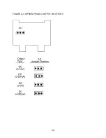
Страница 43: ...39 FIGURE A 3 OPTION PWA DC OUTPUT 2 OUTPUT 3...

Страница 44: ...40...

Страница 45: ...ple 3 Linear DC mA 4 Linear DC V the second digit is Output 1 type 1 Relay the third digit is Output 2 type 0 Output 2 not installed 1 Relay Alarm Only the fourth digit is Output 3 type O Output 3 not...

Страница 46: ...the remote reset option The code may be changed by pressing the UP and DOWN keys The RESET key must be pressed when the correct code is displayed NOTE It is essential that this code is changed whenev...

Страница 47: ...00 1824 C 1938 N 0 1399 C 5371 N 32 2550 F 5324 Factory default For RTD Inputs Note Input conditioning jumper JU1 needs to be changed see Appendix A Also the Hardware Definition Code for the input typ...

Страница 48: ...44...

Страница 49: ...process variable has gone over range RTD and DC mV Type and Connection Three wire Pt100 Calibration Complies with BS 1904 and DIN43760 Lead Compensation Automatic Sensor Break Protection Break detect...

Страница 50: ...etransmit General Types Available Relay or DC linear retransmit only Relay Contact Type SPDT Rating 2A resistive at 120 240V AC Lifetime 500 000 operations at rated voltage current Isolation Inherent...

Страница 51: ...t Lead Resistance 0 1 ohm lead balanced Pt100 Common Mode 120dB at 50 60Hz giving negligible effect at up to Rejection 264V 50 60Hz Series Mode 500 of span at 50 6OHz causes negligible effect Rejectio...

Страница 52: ...0 ohm per lead maximum balanced Pt 100 Temperature Stability 0 01 of Span C change in ambient PHYSICAL Dimensions 1 16 DIN front panel 48mm x 48mm 4 33 inches deep Mounting Plug in with panel mounting...

Страница 53: ...MATRIX 1 1 2 6 OUTPUT 1 1 Relay OUTPUT 2 0 None 1 Relay OUTPUT 3 0 None 1 Relay 3 4 20 mA OPTIONS 0 None 1 RS 485 2 Remote Reset SUFFIX Blank None 02 Line Voltage 24 V AC DC For alarm output only For...

Страница 54: ...50...

Страница 55: ...APPENDIX F SOFTWARE REFERENCE SHEET Hardware Definition Setting HDW DEF OPTION Configuration Mode Setting inPS ACt SPUL SPLL ALA1 ALA2 USE2 USE3 CbS CPAr CAd CJC Enable Mode Setting ENAB ESP ECon ESE...

Страница 56: ...52 Setup Mode Setting HiHd LoHd tLE iCOR Filt Hyst Pou PoL PHAI PLAI PHA2 PLA2 dPoS Euu EuL CCon diSP Setpoint Change Mode Setting SP SPHi SPLo...

Страница 57: ...is Warranty shall be deemed valid and binding upon Despatch if and only if the Customer 1 installs loads operates and maintains the covered product supplied hereunder in accordance with the instructio...

Страница 58: ...and manufacturing documentation specific to your Despatch unit s This exacting level of service is a benefit only Despatch can provide and means that you can expect speedy accurate and the most cost...

Отзывы: