DesignTech AutoCommand 20022 Скачать руководство пользователя страница 4

Page 4

20022

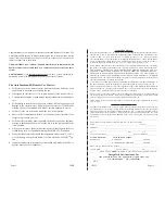
AutoCommand Model 20022

Color

Function

Type

Required

Red/Black

Control Switch

Yes

Red/White

Remote

- Input Yes

Green

Tach

Input

N o

Violet

Hood

- Input Yes

Orange

Brake

+ Input

Yes

Color

Function

Type

Required

Pink

Power(+12V)

Input

Yes

White

Accessory/Lights

Relay output

Yes

Yellow

Starter

Relay output

Yes

Blue

Ignition 1

Relay output

Yes

Green

Ignition 2

Relay output

Maybe

Black

Ground

Input

Yes

Left White Button

Right Red Button

LED

Color

Function

 Type

 Required

Yellow/Green

Alarm Control

(+) 400 mA

N o

Green/White

Sensor IN

Relay

No

Brown

Accessory Pulse

(-) 400 mA

No

Brown/White

Alarm Disable

(-) 400mA

No

Gray/Black

Sensor OUT

Relay

No

Plug-in Control Switch

20022

Page 17

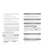
1. Remove the top and bottom halves of the steering column shroud.
2. Locate the small three wire harness (with White, Black and Yellow wires) running down from the

ignition key cylinder on the top right hand side of the steering column into the instrument panel.

3. Cut the Yellow wire in half and bare back the Black wire.
4. With the ignition key in and turned to the “ON” or “RUN” position, measure the resistance be-

tween the key side of the Yellow wire and the Black wire.  Make several measurements to verify
that you have a consistent resistance.  You also need to change your test leads around.  You will find
that you get two different readings.  So far we have found that the higher of the two readings is the
correct resistance.

5. When you have correctly identified the correct resistance obtain a resistance of the same value.
6. Locate the Black “Bulb Test” wire on the left side of the steering column in cavity “D” or “E” of

the Black 5-way connector, just above the main ignition switch connector.

7 . Wire the relay as shown in the following Diagram.

4) New GM PASSLOCK

® 

II Anti-Theft System for 1998 model

vehicles.  

  In 1997 the Malibu/Cutlass and then in 1998 all truck platforms (Full size

Pickup, Suburban, S-10/Sonoma, Blazer/Jimmy, Tahoe/Yukon and Astro/Safari) came out
with this new Passlock II system.

Use the diagram above and the list below to interface to this new type system.  Note that the
Yellow wire for the Passlock is a similar gauge wire to the Starter wire.  Don’t confuse these.

You must acquire a resistor value within 5% of the value of the resistor in the key. Addition-
ally, there is No  BULB TEST wire on this system, so pin 87 is not used.

Substitute as follows:

Wire color above

Trucks

Malibu / Clutlass

‘Black or Yellow’

Yellow

Yellow

‘Black’

Orange/Black

Black

‘Black/White or White’

Red/White

Red/White

Содержание AutoCommand 20022

Страница 1: ...Control Car Starter Model 20022 Installation Manual For use on automatic vehicles only For gasoline or diesel vehicles AutoCommand V 8 3 pcbv7 3 8 1 7955 Cameron Brown Court Springfield Virginia 22153 USA www designtech intl com ...

Страница 2: ...disclaims all other warranties INCLUD ING WITHOUT LIMITATION THE WARRANTIES OF MERCHANT ABILITY AND FIT NESS FOR A PARTICULAR PURPOSE NO PERSON FIRM OR CORPORATION IS AU THORIZED TO ASSUME FOR DESIGNTECH INTERNATIONAL INC ANY OTHER LI ABILITY IN CONNECTION WITH THE SALE AND USE OF THE PRODUCT DesignTech International Inc and agents and distributors will bear no liability whatsoever for incidental ...

Страница 3: ...ing the On Off control switch to the OFF position down every time the car is serviced Show the user how the control switch must be turned off and on again after pulling out the key before leaving the car Give the user a copy of the tan colored page USER TIPS AND NOTES so that they can familiarize themselves with the product USER INFORMATION The brown USER TIPS NOTES sheet gives you further detail ...

Страница 4: ...lack wire Make several measurements to verify that you have a consistent resistance You also need to change your test leads around You will find that you get two different readings So far we have found that the higher of the two readings is the correct resistance 5 When you have correctly identified the correct resistance obtain a resistance of the same value 6 Locate the Black Bulb Test wire on t...

Страница 5: ...wire must only go to the VATS relay If you need IGN2 in the car simply supply power to the IGN2 wire of the vehicle by jumping power from the BLUE IGN1 wire Thus BLUE will be powering up 2 wires behind the key and in some cases 3 wires 2 Diesel Vehicles You must hook the RED BLACK wire up to the diesel glow plug light wire or to the positive side of the vlow plugs itself as described in STEP 18 Th...

Страница 6: ...he key switch Lock Off RUN ACC START ACC 20022 Page 15 C You can choose the next option by pushing the left button again to index to the next option When you get to the next option you want to change simply repeat Step B above After six seconds the AutoCommand automatically exits the programming mode Three LED flashes D Turn the Control Switch back ON and confirm that the LED flashes once as the s...

Страница 7: ...times 3 will add 50 more crank time to No Tach starting 4 adds 100 more crank time This is necessary on many deisel and hard to start vehicles Options 3 and 4 can be added together for even more cranking time 5 is used in the No Tach starting method for some diesel vehicles 6 option must be activated when installing on a diesel vehicle 7 cancels the Enable mode safety feature The Enable mode requi...

Страница 8: ... the red LED on the module will flash 1 to 6 times to identify the problem See the chart below for an explanation of the flashes 1 flash 10 15 minute time out unit should be fine 2 flashes Brake or Hood activated 3 flashes No Tach or Stalled Check tach learning Or confirm that the alternator is being powered up by one of the ignition wires 4 flashes Received another remote input signal 5 flashes T...

Страница 9: ...s the car by reading the engine speed tach information from a wire under the hood If you choose tachometer sens ing connect the GREEN 18 awg wire to the car s tach wire under the hood After you have connected the GREEN wire you need to teach the AutoCom mand the vehicle s tach rate Proceed to step 12A Note You must have already initialized the vehicle Page 12 20022 16 Brown Wire Acc Pulse Control ...

Страница 10: ...t wire can also be triggered by our optional Smart Car Pager accessory which can be controlled from any telephone anywhere in the world This option requires the pager module an activation fee of 25 and a monthly service fee of 3 00 mo 20022 Page 11 OPTIONAL STEPS Many of the optional steps require a relay to be hooked up The most common relay used for this type of application is the Bosch type aut...

Отзывы: