TB-3086
Page 3 of 8
Features and Components
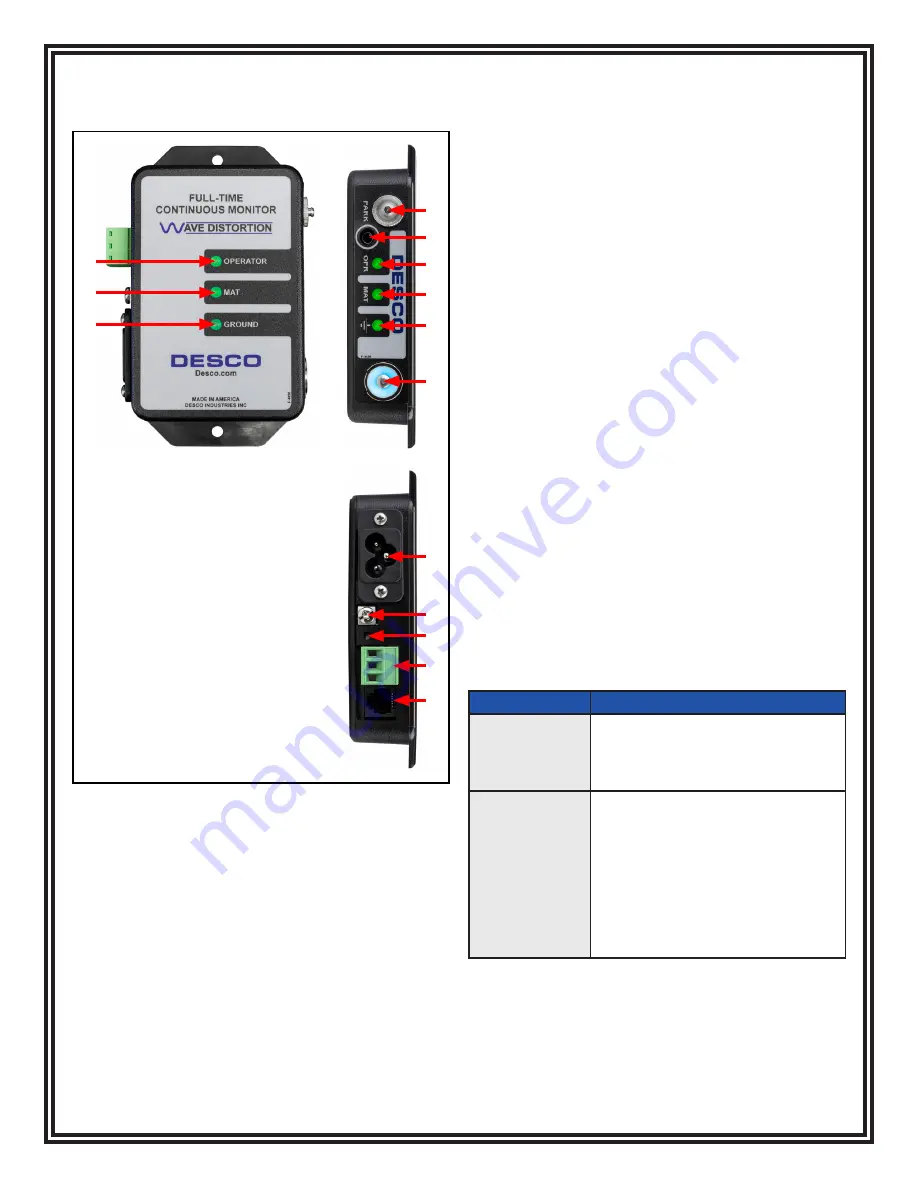
Full-Time Continuous Monitor
Figure 6. Full-Time Continuous Monitor features and
components
A
A. Park Snap:
Allows the operator to disconnect (and
park) a wrist strap when leaving the workstation, without
creating a false alarm. Touch the park snap or park
switch, and the monitor's audible alarm will disable for
approximately 8 seconds. Use this time to disconnect
the wrist cord from the wristband, and attach it to the
park snap or remove the banana plug from the jack.
Upon returning to the workstation and disconnecting
the wrist cord from the park snap, the operator has
approximately 8 seconds to reconnect the wrist cord to
a worn wristband before activating the alarm.
B. Monitored Operator Jack:
Insert the single-wire
wrist cord here to monitor the operator's connection to
ground.
C. Operator LEDs:
Illuminates green when the
operator is properly grounded. Illuminates solid red and
audible alarm sounds when the operator is not properly
grounded.
D. Mat LEDs:
Illuminates green when the worksurface
is properly grounded. Illuminates red and audible alarm
sounds when the worksurface is not properly grounded.
E. Ground LEDs:
Illuminates green when the AC outlet
is properly wired and its path to equipment ground via
the equipment ground conductor is intact. Illuminates
red and audible alarm sounds when the AC outlet is not
properly wired and its path to equipment ground via the
equipment ground conductor is broken.
F. Park Switch:
Allows the operator to disconnect (and
park) a wrist strap when leaving the workstation, without
creating a false alarm. Touch the park snap or park
switch, and the monitor's audible alarm will disable for
approximately 8 seconds. Use this time to disconnect
the wrist cord from the wristband, and attach it to the
park snap or remove the banana plug from the jack.
Upon returning to the workstation and disconnecting
the wrist cord from the park snap, the operator has
approximately 8 seconds to reconnect the wrist cord
to a worn wristband before activating the alarm. The 8
second timer is indicated by the growing intensity of the
park switch's blue LED. The blue LED will pulse when
the operator jack is vacant to indicate standby mode.
G. Power Inlet:
Connect the included power cord here.
H. Mat Monitor Screw Terminal:
Verifies that the
worksurface's path-to-ground is less than 10 megohms.
Connect the white mat monitor cord here.
I. Set Switch:
Toggles the monitor's settings for the
audible alarm and mat monitor circuit.
Function
Procedure
Audible Alarm
Volume
1. Push and release the switch to
toggle the buzzer's volume.
2. The volume will toggle from low,
medium, and high settings.
Enable / Disable
Mat Monitor
Circuit
1. Push and hold the switch until
all LEDs illmuniate orange.
2. Release the switch.
3. An illuminated MAT LED
indicates that the mat
monitor circuit is enabled. A
non-illuminated MAT LED
indicates that the mat monitor
circuit is disabled.
J. Relay Terminal:
Integrates with electronic locks,
lights, buzzers, etc. See the "Relay Terminal" section for
more information.
K. Accessory Jack:
Connects to the 19323 Power
Relay accessory.
C
D
E
B
C
D
E
F
G
H
I
J
K
Test Equipment Depot - 800.517.8431 -
5 Commonwealth Ave,
Woburn,
MA 01801


