TB-3043 Page 3 of 5
© 2009 DESCO INDUSTRIES, INC.
Employee Owned
will change to a steady RED, and the audible alarm will sound
continuously. If the ionizer enters shutdown mode, it must be turned
OFF and then back ON to reset the unit. (See following Calibration
section for more info.)
In the event of circuit failure, the unit will enter shutdown mode.
When the unit enters shutdown mode, ionization will be stopped,
the LED on the front of the unit will illuminate a constant red, and
the audible alarm will continuously sound. The user must then
reset the unit by turning it OFF and back ON.
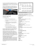
Figure 5 Cleaning the Emitter Points
Cleaning the Emitter Points
Turn electrical power OFF.
I. Turn the unit OFF and unplug the power cord.
II. Remove the rear screen by removing the 4 screws.
See Figure 5
III. Clean the emitter points using the included 60506
Emitter Point Cleaners or a swab dampened with
Isopropyl alcohol
IV. Reattach the rear screen.
V. Plug in the power cord and turn the unit ON.
VI. Verify the offset voltage balance of the ionizer by
using a charge plate monitor or ionization test kit.
The emitter electrodes should not require replacement during the
life of the unit with normal handling. If necessary, item 60507
Replacement Emitter Points are available for order.
ESD TR53 does not advise a test frequency for ionizers. Your
maintence schedule will depend on the requirements of your
ESD Control Plan. In order to manage service intervals, Desco
recommends assigning a number or other identification method for
each ionizer in your Maintence / Calibration schedule. You may
choose to use the ionizer’s serial number for identification, as it is a
unique number for identification, as it is a unique number that can
be traced to when the ionizer was manufactured.
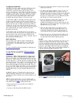
Neutralization (Discharge) Times
The comparative efficiency of overhead ionizers is determined by a
standard test published by ANSI/ESD S3.1. Typical positive and
negative discharge times (in seconds from 1000 volts to 100 volts
and from -1000 volts to -100 volts) measured using this standard
are shown below. The performance of the ionizer was measured
with the unit positioned as shown, with the fan speed on high, and
without a filter.
The typical discharge times measured using this standard for
the ionizer are shown in the following diagram. They are not
guaranteed maximum discharge times
Note: Reference ANSI/ESD STM 3.1. At room ambient temperature
and relative humidity.
Specifications:
AIR FLOW
Three speed fan (125 fpm - 250 fpm, 50 cfm - 100 cfm)
OFFSET VOLTAGE BALANCE
±3 Volts Typical
±5 Volts Typical
(Temperature Range: 65°F - 80°F, RH: 15% - 65%)
CHASSIS
Powder coated aluminum housing
DIMENSIONS (with stand)
9.5" H x 6.0" W x 3.1" L (24cm H x 15cm W x 8cm L)
EMITTER POINTS
.050" diameter
Made of pure tungsten for improved mechanical strength and
ionization stability
FUSE
250 mA slow blow
HIGH VOLTAGE POWER SUPPLY
5.5 kV DC nominal
INPUT POWER
AC line power
Internally selectable for 110/115 VAC - 50/60Hz or
220/230 VAC - 50/60Hz
ION EMISSION
Steady-state DC with sense feedback
MOUNTING
Bench Top tilt adjust frame
OZONE
< 0.05 ppm
WEIGHT
4.5 lbs (2.04 kg)
Figure 6. Neutralization (discharge) times
© 2010 DESCO INDUSTRIES INC.
Employee Owned

