background image


TB-6534

  Page 2 of 8


Revision 4/06


© 2006 DESCO INDUSTRIES INC.                                       

Employee Owned


50664/50665 & 50671/50672 

 OVERHEAD ZERO VOLT IONIZER 

Installation, Operation, and Adjustment Instructions 


The Overhead Zero Volt Ionizer combines the effectiveness of steady-state DC 

ionization with ease of adjustability, communication capability, and the flexibility of a micro-
controller based design to produce a versatile and stable ionization system.  Three fans 
produce extended ionization coverage, and are ideal for areas where bench space is limited.  
(

Note:

  for the 2 fan unit, disregard any instructions relating to the 3 fan unit or fan 3. 


Optional network software and remote control (ZVI-IR) for adjustments are available. 


Installation 


Remove the ionizer from the carton and inspect for shipping damage.  Included with the unit 
are: 


1.  50664/50665 or 50671/50672 Overhead Ionizer 
2.  AC Power Cord 
3.  Keys (to power on) 
4.  Hanging Kit  
 

The AC input voltage should be set to the user’s specification prior to shipping (120v or 

220v).  It can be verified or reset by referring to the 

Maintenance / Cleaning

 section of these 

instructions. 
 

Before installing unit verify that the AC outlet is properly connected to earth ground.  

The unit must have a good earth ground to maintain proper balance.  Install the unit in the 
desired location, making sure that the airflow will not be restricted through the unit.  Make sure 
the ON/OFF key switch, located on the side of the unit, is in the “OFF” position.  Plug the 
power cord into the unit and then into the appropriate AC power source.  This equipment has a 
grounding type plug that has a third (grounding) pin.  This plug will only fit into a grounding 
type power outlet.  If the plug does not fit into the outlet, contact qualified personnel to install 
the proper outlet.  Do not alter the plug in any way. 


Setup and Operation


The unit is powered on and off by using the keys supplied with the unit.  The key switch 

is located on the left end of the unit along with the RS485 input/output ports for the optional 
ZVI software package. The control buttons along with the LED display are located on the front 
of the unit.  The control buttons are numbered left to right as shown in Figure 1.  Button #1 (

W

Содержание 50664

Страница 1: ...2006 DESCO INDUSTRIES INC Employee Owned 50664 50665 120V 50671 50672 220V OVERHEAD ZERO VOLT IONIZER Installation Operation and Adjustment Instructions 3651 Walnut Avenue Chino CA 91710 Phone 909 627 8178 Fax 909 627 7449 DescoEMIT com ...

Страница 2: ...r 220v It can be verified or reset by referring to the Maintenance Cleaning section of these instructions Before installing unit verify that the AC outlet is properly connected to earth ground The unit must have a good earth ground to maintain proper balance Install the unit in the desired location making sure that the airflow will not be restricted through the unit Make sure the ON OFF key switch...

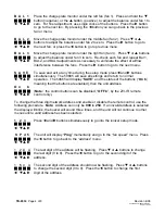
Страница 3: ...imultaneously to get into the ionizer setup mode J J J J When the buttons are released the unit should beep once and Prog should W T S X appear momentarily on the LED display The display will then move to the fan speed settings S P d 5 Press T or S buttons to adjust the fan speed from SPd 1 lowest to SPd 9 J J J J highest for operator comfort and satisfactory decay times Press the X button W T S X...

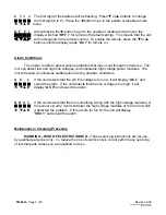
Страница 4: ...s J J J J simultaneously The 50665 will save all settings and return to normal W T S X operation The 50665 will display SAVE and the status of the buttons On b meaning that the buttons are enabled then the unit address O n b J J J J Note the control buttons can be disabled OFF b by the ZVI IR remote W T S X control only To change the three digit network address and enable or disable the remote con...

Страница 5: ...w and high line voltages and inoperable high voltage power modules The unit will sound a continuous audible alarm during all alarm conditions A C L If the unit detects that the AC line voltage is too low it will display AC L and J J J J sound the alarm If the unit detects that the line voltage is too high it will W T S X display AC H and sound the alarm S H d 1 If the unit detects that there is so...

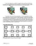
Страница 6: ...t the ribbon cable connector from the socket and lift the fan module out The eight emitter points can be easily cleaned using Semtronics part number S204 200 emitter point cleaner or 99 rubbing alcohol and a clean brush To clean any excess dirt off of the fan and or fan guard it is recommended to use compressed air Once the fan modules are clean slide them back onto the alignment posts connect the...

Страница 7: ...al 0V 5 volts maximum Dimensions 3 1 2 D x 6 1 2 W x 42 L Emitter Points Machined Tungsten Fuse 400 mA slow blow High Voltage Power Supply 5kV Input Power 115V AC 60Hz or 220 230V AC 50Hz Internal Jumper Selectable Ion Emission Steady State DC Ozone Less than 0 05ppm Weight 10 pounds Area of Optimum Charge and Neutralization for 50671 and 50672 ...

Страница 8: ...f your original packing slip invoice or other proof of date of purchase Any unit under warranty should be shipped prepaid to the Desco EMIT factory Warranty replacements will take approximately two weeks If your unit is out of warranty Desco EMIT will quote repair charges necessary to bring your unit up to factory standards Call Customer Service at 909 627 8178 for proper shipping instructions and...

Отзывы:

Похожие инструкции для 50664