background image

TB-6502

  Page 4 of 8


Revision May 2007


© 2007 DESCO INDUSTRIES INC.                                          

Employee Owned


Installation 


Mount the tester in the desired location using the four mounting holes in the corners of the 
sign. 
 
Set the foot plate below the tester. 
 
Insert one stereo plug of the 50405 Stereo Plug to Stereo Plug into the stereo jack on the 
bottom of the tester.  (See Figure 1.)  Insert the other end of the stereo plug into the stereo 
jack at the back of the foot plate.  Verify that both plugs are fully inserted and tight. 
 
* Jack is located under foot plate at upper center of foot plate.


Figure 1, Bottom View 

 
Insert the banana plug end of the R391 Banana Plug to Ring Tongue into the “GROUND” 
jack on the bottom of the tester.  (See Figure 1.)  Connect the other end of the cable to earth 
ground.  Verify that both connections are tight.  Failure to correctly ground the tester could 
significantly degrade the accuracy of the measurement. 
 
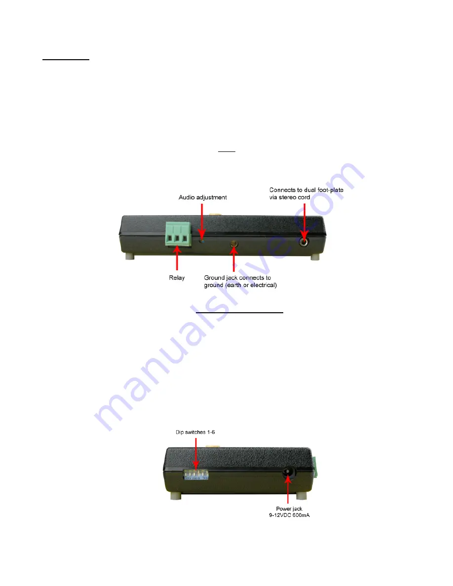
Verify that the power supply is the appropriate voltage for your location.  Insert the power 
supply plug into the “POWER” jack on the left side of the tester making sure that the plug is 
fully inserted into the jack and tight. (See Figure 2.)    Plug the power supply into a convenient 
power outlet. 


Содержание 50407

Страница 1: ...y 2007 2007 DESCO INDUSTRIES INC Employee Owned 50407 50413 DUAL INDEPENDENT FOOTWEAR AND WRIST STRAP TESTER INSTALLATION AND OPERATING INSTRUCTIONS 3651 Walnut Avenue Chino CA 91710 Phone 909 627 8178 Fax 909 627 7449 DescoEMIT com ...

Страница 2: ...g of the wrist strap includes the resistance of the groundable point on the end of the cord the cord itself the resistor the cord to cuff snap connector the resistance of the interface of the cuff the cuff wrist interface and the resistance of the person between the wrist and the hand that contacts the test electrode Per ESD Handbook TR 20 20 paragraph 5 3 2 2 2 Wrist Strap Ground Cord At first gl...

Страница 3: ... High Limit Resistance ON ON 10 Megohms 1 X 10E7 OFF OFF 35 Megohms 3 5 X 10E7 DEFAULT EUROPE ON OFF 100 Megohms 1 X 10E8 DEFAULT USA OFF ON 1 Gigohm At 1 Gigohms high limit resistance a dirty footplate could result in a false pass When using this setting special care must be taken to keep the footplate clean DIP switches 3 4 control the LOW limit for the footwear test selection as follows Switch ...

Страница 4: ...ght Jack is located under foot plate at upper center of foot plate Figure 1 Bottom View Insert the banana plug end of the R391 Banana Plug to Ring Tongue into the GROUND jack on the bottom of the tester See Figure 1 Connect the other end of the cable to earth ground Verify that both connections are tight Failure to correctly ground the tester could significantly degrade the accuracy of the measure...

Страница 5: ...rts the test During the test all LEDs will be OFF to indicate that a test is in progress The touch plate must remain depressed until the test results are displayed Depending on the configuration of the tester the test could require up to three 3 seconds The resistance is checked from the touch plate to the corresponding foot plate for each foot and from the touch plate to the wrist strap connector...

Страница 6: ...icating the failed test will be displayed for approximately three 3 seconds and the internal relay will not activate CALIBRATION AND PERIODIC TESTING The accuracy of the 50407 50413 is specified as 1 5 for 1 Megohms and lower resistance ranges 2 10 for 1 Megohms and higher resistance ranges A periodic check once every 6 to 12 months using a precision resistance box should be performed to verify pr...

Страница 7: ...propriate on the 50401 50407 50413 and repeat the test The results of the test should be fail high for the wrist strap Footwear operation test 1 Insert the 50401 50407 50413 test plug into the foot plate cable connector on the 50407 50413 2 Select the appropriate fail low range on the rotary switch of the 50401 50407 50413 3 Press and hold the touch plate of the 50407 50413 until the test is compl...

Страница 8: ...e include a copy of your original packing slip invoice or other proof of date of purchase Any unit under warranty should be shipped prepaid to the Desco EMIT factory Warranty replacements will take approximately two weeks If your unit is out of warranty Desco EMIT will quote repair charges necessary to bring your unit up to factory standards Call Customer Service at 909 627 8178 for proper shippin...

Отзывы: