background image

-  21  - 


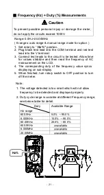
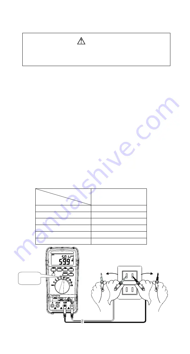
Frequency (Hz) + Duty (%) Measurements 


Caution 

To  prevent  possible  personal  injury  or  damage  the  meter, 

do not apply the circuits exceed 1000V. 

Range: 0.0Hz~20.00MHz   

( 6 ranges: auto range & manual range mode for option ) 

1.  Set rotary 

to “ 

Hz %

 position. 

2.  Plug black  test  lead into the COM terminal and red test 

lead into the


V


terminal. 

3.  Connect test leads to the circuit to be tested. Allow time 

for  values  stabilize  and  then  read  the  frequency  of  AC 
measurement on the LCD. 

4.  The  corresponding  duty  of  the  frequency  value  syncs 

displaying on sub-display. 

5.  When finished, turn rotary switch to OFF position to turn 

off the meter. 
 

Note:   

1.  The voltage detected is too small which will not allow 

frequency to be detected and displayed properly. 

2.  Duty cycle range is variable at different Frequency range, 

see below table for detail. 

                  Duty 

Hz range 

Available Range 

600.0Hz 

5.0% 

95.0% 

6.000KHz 

10.0% 

90.0% 

60.00KHz 

20.0% 

80.0% 

600.0KHz 

    unavailable


6.000MHz 

    unavailable


20.00MHz 

    unavailable


Hz%


Содержание DE-5003

Страница 1: ...sing our products Please read this instruction manual before using the meter and keep it properly for contingent use 7F No 351 Sec 2 Chung Shan Rd Chung Ho Dist New Taipei City 23504 Taiwan TEL 02 222...

Страница 2: ...31...

Страница 3: ...AX MIN HOLD 12 Integrate REL MAX MIN HOLD 12 13 DQ 13 Buttons vs Measuring Functions 14 5 Measurement Functions 15 23 Measuring AC Voltage 15 Measuring DC Voltage 16 Measuring DC AC Millivoltage mV 17...

Страница 4: ...s may result in damage to the meter or other equipment Dual Insulation AC Alternating Current DC Direct Current Grounding Earth Terminal Fuse Warning Set the function switch and function key at the pr...
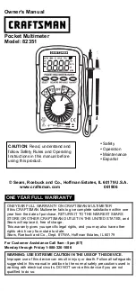
Страница 5: ...g may occur When finished measurement turn the function switch back to OFF position to turn off the meter completely There is minor power exhaustion if the meter is power off by auto power off functio...
Страница 6: ...CAT III Measurements in building installations stationary consumers distributor terminals devices connected permanently to the distributor CAT IV Measurements at power sources for low voltage installa...

Страница 7: ...crystal display LCD Display measuring symbols units and readings Refer to functions at page 6 7 Buttons Refer to functions at page 9 13 Function switch Refer to functions at page 8 Range label Indica...

Страница 8: ...nput terminal for AC microampere milliampere or DC microampere milliampere measurement COM for black test lead Input terminal for all measurements V LCR for red test lead Positive input terminal for v...

Страница 9: ...oltage millivoltage voltage A mA A Units of current microampere milliampere and ampere LCR L C R measurement mode Ls Lp Inductance in series or parallel mode is active Cs Cp Capacitance in series or p...

Страница 10: ...sistance Continuity Diode measurement initial function is Resistance Hz Frequency Duty measurement LCR Inductance Capacitance Resistance Measurement initial function is Inductance A DC AC microampere...

Страница 11: ...nt as list Shift ranges as below table Rotary SW position Press RANGE button to shift ranges Initial range 6 000V 60 00V 600 0V 1000V 6 000V 6 000V 60 00V 600 0V 1000V 6 000V 600 0 6 000k 60 00k 600 0...

Страница 12: ...nt HOLD Press HOLD button to retain data during measuring symbol displays and freeze the reading Press HOLD again to resume normal measuring mode In Hold mode either REL or MAX MIN button is disabled...

Страница 13: ...Press REL Relative Value Press HOLD Press HOLD Retain Relative Value Integrate REL MAX MIN Press REL button during measurement to enter Relative mode display The reference value is stored and display...

Страница 14: ...REL MAX MIN HOLD In REL MAX MIN mode press HOLD button to enter REL MAX MIN HOLD mode to freeze the values and mode Press MAX MIN button to shift reading Maximum Relative and Minimum Relative and the...

Страница 15: ...s Parameter on sub display In C Capacitance test mode D in cycle In L Inductance test mode Q in cycle In normal operation Display Min Relative value Display Relative value Display Max Relative value D...

Страница 16: ...14 The following table lists the available button function versus every measurement mode Button function SELECT RANGE HOLD MAX MIN REL CAL DQ mV Hz Duty LCR Note available unavailable...

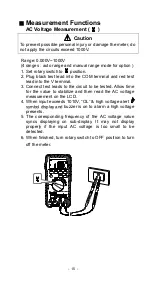
Страница 17: ...ead into the V terminal 3 Connect test leads to the circuit to be tested Allow time for the value to stabilize and then read the AC voltage measurement on the LCD 4 When input exceeds 1010V OL high vo...

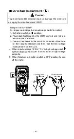
Страница 18: ...ug black test lead into the COM terminal and red test lead into the V terminal 3 Connect test leads to the circuit to be tested Allow time for the value to stabilize and then read the DC voltage measu...

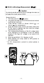
Страница 19: ...for measurement 4 Apply test leads to the circuit to be tested Allow time for the value to stabilize and then read the voltage measurement on the LCD 5 The corresponding frequency of the AC voltage va...

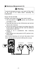
Страница 20: ...lug black test lead into the COM terminal and red test lead into the terminal 3 Connect test leads to the object to be tested Allow time for the value to stabilize and then read the resistance measure...

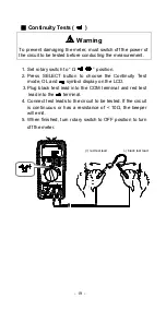
Страница 21: ...LECT button to choose the Continuity Test mode OL and symbol display on the LCD 3 Plug black test lead into the COM terminal and red test lead into the terminal 4 Connect test leads to the circuit to...

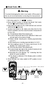
Страница 22: ...reading approximately 0 2 0 3V If the reading is near to 0 means short circuit If LCD displays OL means open circuit B Reverse bias Diode Test drawing Connect black test lead to the anode of diode an...

Страница 23: ...for values stabilize and then read the frequency of AC measurement on the LCD 4 The corresponding duty of the frequency value syncs displaying on sub display 5 When finished turn rotary switch to OFF...

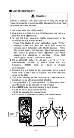
Страница 24: ...L button to process short calibration until PASS displays the calibration is complete Press REL button again to enter LCR measurement 4 Press SELECT button to choose L or C or R for measurement Parall...

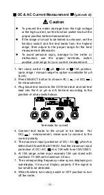
Страница 25: ...able for A mA 2 Press SELECT button to choose AC or DC for measurement 3 Plug black test lead into the COM terminal and red test lead into the A or A or mA terminal according to the position of rotary...

Страница 26: ...sumption after the A P O For power saving please always turn the function switch to OFF position after finished the measurement Hold SELECT button and to turn on the meter The A P O function will be c...

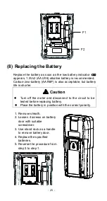
Страница 27: ...battery life is shorter Caution Turn off the meter and disconnect to the circuit to be tested before replacing battery Place the battery in position with the correct polarity 1 Remove sheath 2 Loosen...

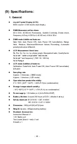
Страница 28: ...est mode Auto set test frequency 100 1K 10K Hz Auto Range LCR mode Additional features Calibration Data Hold Auto Power Off Auto Power Off Cancellation Backlit Sampling rate Approx 3 times sec DMM mod...

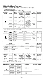
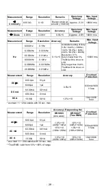
Страница 29: ...mpedance Max Input Voltage DE 5003 DE 5004 DCV 6 000V 0 001V 0 1 3 Approx 11M 1000V rms 60 00V 0 01V 0 2 3 Approx 10M 600 0V 0 1V 0 4 3 1000V 1V 0 6 5 VA Hz at secondary display Accuracy Max Input Vol...

Страница 30: ...on LCD 1000V rms 6 000kHz 0 001kHz 60 00kHz 0 01kHz 600 0kHz 0 1kHz 6 000MHz 0 001 MHz 20 00MHz 0 01MHz Measurement Range Resolution Accuracy Overload Protection DC A 600 0 A 0 1 A 0 5 5 630mA 1000 V...

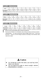
Страница 31: ...LCR Resistance Rs Rp 0 01 60 0 60 1 600 0 601 6000 6 01 60 00K 60 1 600 0K 601 6000K 6 01 20 00M Resolution 0 1 0 1 1 0 01K 0 1K 1K 0 01M Accuracy 1 0 20 0 3 5 0 3 5 0 3 5 0 3 5 1 0 5 3 0 5 Above acc...

Страница 32: ...uce meters in various types and specification and all our products conforms to ISO standards If any further inquiry needed please visit our website at www deree com tw Specifications and external appe...

Отзывы: