4
5
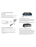
iPod Dock cable or
cradle or DAB+G
connector
Connector port
(optional)
USB device
Microphone
Connector port (optional accessory)
The Connector port allows easier access to the USB and AUX connections
of the Gateway, and provides a bypass switch and an easy reset option.
The iPod connection and charging is possible directly through the iPod
dock cable or an iPod cradle (not included).
Please fix the Connector port in a position where the user can access the
inputs, and leave sufficient room for attaching USB storage devices.
6. INSTALLATION (PART 2)
There are DIP switches on the bottom of the Gateway Pro BT. You can
activate / deactivate the hands free functionality with DIP switch 5. Change
the default settings only if you want to use the factory fitted phone options.
For example: If you want to use the factory phone option instead of the
Pro BT, set DIP switch 5 ON and change the 4-pin molex (phone audio)
position as it can be seen below (as it can be seen on the picture next page).
The other DIP switches between 1 - 4 are non-functional.
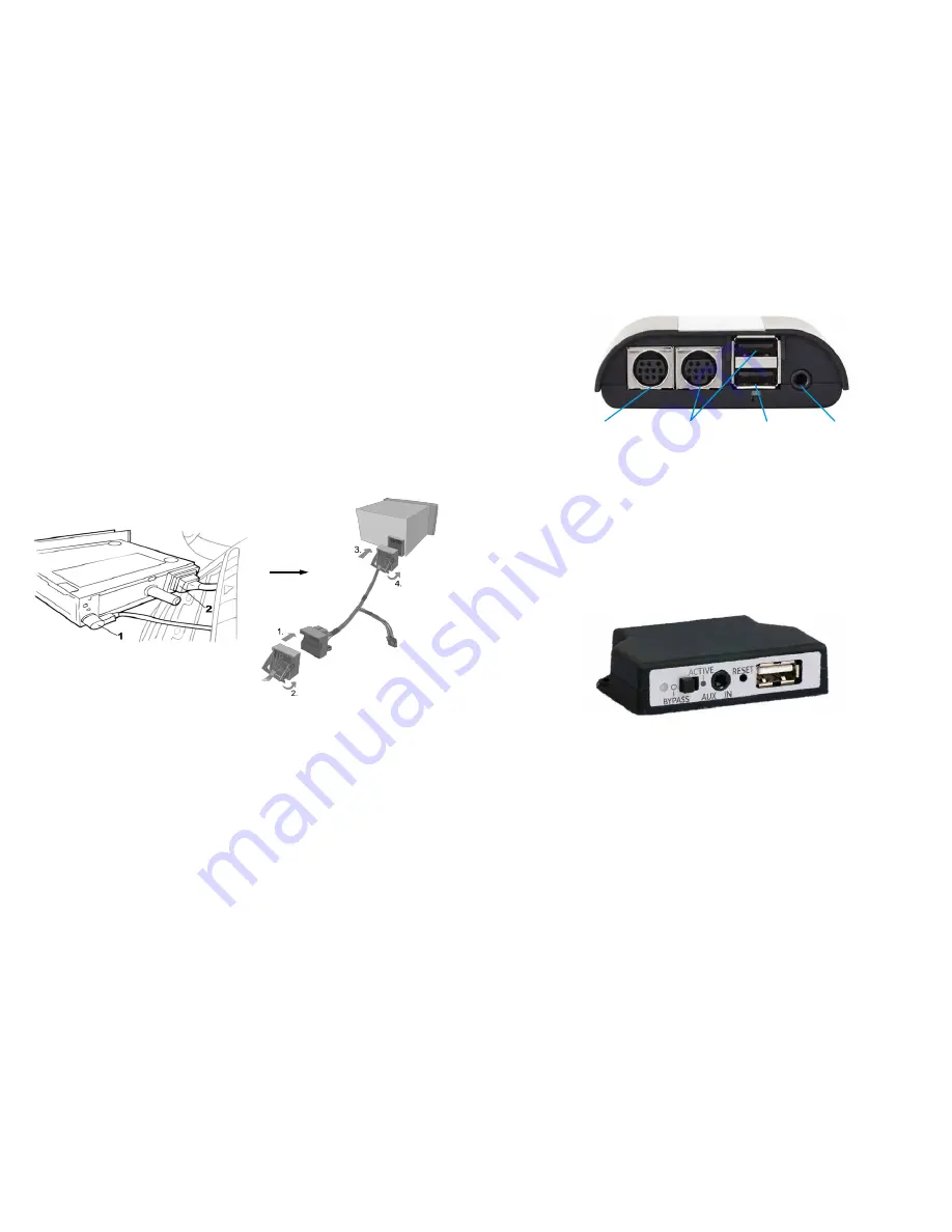
4. FITTING THE GATEWAY
HARNESS
Once the head unit is removed, disconnect the antenna cable (1), and then
unclip the main wiring connector from the head unit (2).
With the main radio cable removed, connect the Dension supplied cable
between the original factory cable harness and the head unit.
5. INSTALLATION (PART 1)
The below diagram depicts how the different modules connect to the
Gateway Pro BT.
► Connect the 18 way Micro-Fit to the car side of the Gateway Pro BT
module.
► Connect the round iPod connector (optional) and Connector port
(optional) to the module and feed them through the dashboard to
an appropriate location.
Содержание Gateway Pro BT
Страница 1: ...INSTALLATION AND USER MANUAL FOR GATEWAY PRO BT...
Страница 9: ...GWP 9206 2...


