20
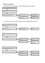
TROUBLE SHOOTING
1. The power can not be turned on. (Power indication LED does not light.
)
2.2.
2.3.
Check the insertion of the 8U-110132-6 AC UNIT.
Set remains in standby mode with power indicato
LED lit red.
Check the insertion of the 8U-110132-2 UCOM
UNIT.
Power indicator LED remains flashing red and
muting mode is not canceled (protection mode is
set).
Set operates, but then power indicator LED
flashes red (protection mode is set).
Check each connector.
Check whether power is being supplied to the
coil of the standby transformer (T101).
Check the power amplifier output's offset voltage.
Check the power amplifier output's offset voltage.
Power not supplied.
Offset voltage output is 1V
or greater.
Offset voltage output is 1V
or greater.
The connectors are
inserted completely.
Broken wire in standby
transformer (T101).
Damaged power amplifier
circuit.
Damaged power amplifier
circuit.
Malfunction of, U601 or
S101.
Power supplied.
No offset voltage is output.
No offset voltage is output.
Malfunction of D101-106,
C105 or C106.
Damaged temperature
detection circuit or
protection circuit.
Check the bias current.
2. The power turned on, but a sound does not output normally. (Both channels)
Содержание PMA-2020AE
Страница 10: ...10 Wire arrangement viewed from the bottom Front Panel side Back Panel side...
Страница 13: ...13 2 Remove the screws 3 Remove the screws then remove the solder...
Страница 22: ...22 BLOCK AND LEVEL DIAGRAM AUX NETWORK...
Страница 23: ...23 WIRING DIAGRAM...
Страница 50: ...50 Personal notes...


