DENISON HYDRAULICS
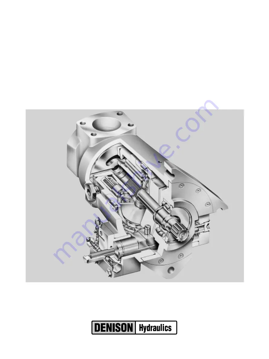
Premier Series
P05 open loop pump controls
service information
Publ. S1-AM028
Internet: http://www.denisonhydraulics.com E-mail: denison@ denisonhydraulics.com
www.comoso.com
Страница 1: ...DENISON HYDRAULICS Premier Series P05 open loop pump controls service information Publ S1 AM028 Internet http www denisonhydraulics com E mail denison denisonhydraulics com www comoso com ...
Страница 2: ...r disassembly assembly test figure 11 parts list hydraulic stroker torque limiter parts list torque limiter disassembly assembly figure 12 torque limiter figure 13 torque limiter cap parts lists for figure 12 and figure 13 torque limiter test and adjustment rotary servo parts list rotary servo disassembly assembly test figure 14 parts list rotary servo load sensing control parts list load sensing ...
Страница 3: ...008 8 provided Jupiter driver S20 14078 Jupiter power supply S20 11715 Options card S20 ll716 Venus controller 020 14103 electric stroker nominal coil resistance 24v coil electric stroker nominal coil resistance 12v coil handwheel turns full to zero stroke torque to turn handwheel 1000 psi 70 bar torque to turn handwheel 7250 psi 500 bar port C1 C2 cylinder gage ports port E electric stroker contr...
Страница 4: ...ement must reduce and vice versa A linkage to the pump control piston slides a spool over a pin The pin contains a cross drilled hole and a connecting drilling to one end This pin passes through a bore in the torque limiter housing connecting to the vent port of the compensator The pressure in the vent port applies a force on the pin which is resisted on the other end by a two spring combination T...
Страница 5: ...ntial adjustment Differential set too high control valve Poor control of flow Differential adjustment Differential set too low Torque Limiter Torque Limiter Override Torque setting erratic Torque limiter cap malfunction Sticking pin Torque incorrect at high flows Incorrect torque setting Outer adjustment screw Torque incorrect at low flows Incorrect torque setting Inner adjustment screw Too much t...
Страница 6: ...Buck Up Cap Fig 4 S22 15447 1 1 4 Screw H H C M12 x 55 mm 363 12205 8 6 5 Screw H H C M12 x 75 mm 363 12220 2 6 Control Piston 032 91836 1 1 7 O Ring 70 S 1 ARP 013 671 00013 2 2 8 O Ring 70 S 1 ARP 151 671 00151 2 2 9 Piston Ring 032 91816 2 2 includes items 1 4 5 CCW ROTATION CW ROTATION C10 C20 PRESSURE COMPENSATOR parts list 1 2 4 3 4 3 1 4 2 4 1 5 2 3 4 3 5 1 2 4 6 7 8 9 ITEMS NOT SHOWN www c...
Страница 7: ... pivots on ball 8 and is retained by pressing two balls 9 into screw 2 Replace assembly if damaged ASSEMBLY 1 Install ball 8 and seat 10 in screw 2 2 Press balls 9 into screw 2 to retain seat 3 Install O ring 6 on screw 2 Lubricate O ring and slide screw into bracket 1 Install remaining parts 4 Turn handwheel clockwise into cap till the screw contacts the control piston 5 Install and torque the as...
Страница 8: ...ntrol piston 1 Install gages on system pressure and on compensator vent port V 2 Turn compensator adjustment screw 25 CCW until there is no contact with spring then adjust 1 2 turn CW after contact is made with spring 3 Turn differential adjustment screw 3 CCW until there is no contact with spring then adjust 1 2 turn CW after contact is made with spring 4 System relief valve should be set at 500 ...
Страница 9: ... 90 S 1 ARP 910 691 00910 2 14 O Ring 90 S 1 ARP 017 691 00017 1 15 Plug 031 57368 1 16 Seal Piston 032 91305 1 17 Cap 449 00612 1 18 Spool 032 59482 1 19 Orifice Plug 033 25528 1 21 Plug SAE 8 488 35018 1 22 O ring 90 S1 ARP 908 691 00908 1 25 Soc Setscrew 5 16 24 x 1 1 4 312 13180 1 26 Acorn Nut 036 33474 1 28 Plug SAE 4 488 35061 2 29 O ring 90 S1 ARP 904 691 00904 2 PRESSURE COMPENSATOR 9 FIGU...
Страница 10: ...and piston 1 2 Install O rings on interface between cap and pump control pad Install cap assembly on pump housing as indicated on the applicable view guiding the control piston into the bore 3 Torque the assembly bolts to 75 ft lbs 102 Nm P05 ITEM DESCRIPTION PART NO QTY 1 Piston 032 92202 1 2 Spring 032 92205 1 3 Sleeve 032 92203 1 4 Control Cap 032 91832 1 5 O Ring 691 00920 1 6 Plug 032 92204 1...
Страница 11: ...864 1 1 1 1 Tube CCW 032 92049 6 Screw H H C M12 x 55 mm 363 12205 6 4 4 6 7 Screw H H C M12 x 75 mm 363 12220 2 4 4 2 8 Control Piston 032 91785 1 1 1 1 9 O Ring 70 S 1 ARP 013 671 00013 2 2 2 2 10 O Ring 70 S 1 ARP 151 671 00151 2 2 2 2 11 Piston Ring 032 91816 1 1 1 1 12 Piston Ring 032 91811 1 1 1 1 Included with items 1 2 ELECTRIC STROKER parts list 4 3 7 1 2 5 6 1 7 4 3 5 2 6 4 3 7 1 2 5 6 1...
Страница 12: ...on and torque to 5 ft lb 6 8 N m 9 Install minimum stop screw 24 and turn clockwise to stroke pump to full volume Measure height from control cap to top of screw 3 With control piston at full stroke dimension must be 0 75 03 in 19 2 0 76 mm Back out minimum stop screw 24 till there is no contact with control piston 10 Press dowel 30 into body 16 through the link 28 to 0 25 in 6 35 mm below surface...
Страница 13: ...and 414 bar system pressure Pump stroke should follow amperage smoothly and proportionally Full to zero or zero to full stroke should be achieved in 0 7 second Adjust amperage up to 275 mA from zero stroke then adjust down from full stroke to 275 mA The flows at the two 275 mA settings shall not vary more than 2 5 gpm 10 l m from each other ELECTRIC STROKER 13 FIGURE 5 ELECTRIC STROKER FIGURE 6 SE...
Страница 14: ...71 00011 2 36 Block 032 91509 1 37 Screw HHC 1 4 20 x 2 1 4 306 40187 3 38 Plug Alum 449 00013 1 39 O Ring 90 S 1 ARP 908 691 00908 2 41 Prop Pr Cont Valve 517 00095 1 42 Coil 24VDC 517 00096 1 43 Connector 167 01008 8 1 44 O Ring 90 S 1 ARP 904 691 00904 1 45 Plug SAE 4 488 35061 1 46 Screw SHC 10 32 x 1 4 312 09041 2 47 O ring 70 S 1 ARP 010 671 00010 1 ITEM DESCRIPTION PART NO QTY 1 Cap Sleeve ...
Страница 15: ... cover 5 and Max volume screw 4 2 Remove 4 screws holding cap to pump 3 Remove cap assembly from pump 1 Install O rings on interface between cap and pump control pad Install cap on pump housing as indicated on the applicable view guiding the control piston into the bore 2 Torque the assembly bolts to 75 ft lbs 102 Nm 3 Install screw 4 in cap Install O ring 3 on nut 5 Install nut 5 on screw 3 Adjus...
Страница 16: ...in cap 1 being careful that cone enters seat 10 Install adj plug 2 screw 25 nut 4 and acorn nut 26 6 Install plug 12 and torque to 90 ft lb 122 Nm Install plug 21 Torque to 50 ft lb 68 Nm Install plug 28 Torque to 11 ft lb 15 Nm 7 Carefully install O ring 30 into the cap 8 Note proper location for cap Install O rings on interface between cap and pump control pad Install cap assembly on pump guidin...
Страница 17: ...ctite hyd sealant loctite 242 torque 5 ft lb 6 8 Nm FIGURE 9 TORQUE LIMITER OVERRIDE CAP differential adjustment port C1 cylinder pressure port SAE 4 torque 11 ft lb 15 Nm system pressure SAE 10 torque 90 ft lb 122 Nm compensator adjustment servo pressure from opposite cap SAE 6 port V compensator vent SAE 8 torque 50 ft lb 68 Nm www comoso com ...
Страница 18: ...35 1 1 30 Dowel Pin 1 8 Dia x 1 50 Lg 324 20824 1 1 33 Screw SHC 10 32 x 1 4 312 09041 2 2 34 Nut 032 91645 1 1 35 O Ring 70 S 1 ARP 010 671 00010 1 1 PARTS LIST FOR FIGURE 8 torque limiter override code J S22 15405 code K S22 15630 TORQUE LIMITER OVERRIDE ITEM DESCRIPTION PART NO QTY 1 Cap Sleeve Assembly S22 15445 1 2 Adj Plug 032 91814 1 3 Soc Setscrew 5 16 24 x 1 312 13160 1 4 Nut 5 16 24 335 ...
Страница 19: ...i and 6000 psi 207 bar 414 bar and 500 bar At each condition increase the system pressure until the pump fully de strokes At no time should the system pressure vary more than 150 psi 10 3 bar from the compen sator setting The control should be steady and stable at all conditions 11 Reduce pressure to 150 psi 10 3 bar below the compensator setting Pump should return to full stroke Repeat two or mor...
Страница 20: ... and on compensator vent port V 2 Turn compensator adjustment screw 25 CCW until there is no contact with spring then adjust 1 2 turn CW after contact is made with spring 3 Turn differential adjustment screw 3 CCW until there is no contact with spring then adjust 1 2 turn CW after contact is made with spring 4 Start prime mover with system relief valve set at 500 psi 35 bar Apply a load to the pum...
Страница 21: ...rifice 033 25528 1 20 Nut M16 032 91822 1 21 Plug 488 35018 2 22 O ring 90 S 1 ARP 908 691 00908 2 23 O ring 70 S 1 ARP 115 671 00115 1 24 Soc setscrew 311 50001 1 25 Soc Setscrew 5 16 24 x 1 1 4 312 13180 1 26 Acorn Nut 036 33474 1 27 Plug 449 00015 1 28 Plug SAE 4 488 35061 2 29 O ring 90 S 1 ARP 904 691 00904 2 COMPENSATOR OVERRIDE PARTS LIST FOR FIGURE 10 compensator override control S22 15404...
Страница 22: ...15017 2 2 2 2 5 Tube CW 032 91864 1 1 1 1 Tube CCW 032 92049 6 Screw H H C M12 x 55 mm 363 12205 6 4 4 6 7 Screw H H C M12 x 75 mm 363 12220 2 4 4 2 8 Control Piston 032 91785 1 1 1 1 9 O Ring 70 S 1 ARP 013 671 00013 2 2 2 2 10 O Ring 70 S 1 ARP 151 671 00151 2 2 2 2 11 Piston Ring 032 91816 1 1 1 1 12 Piston Ring 032 91811 1 1 1 1 Included with items 1 2 4 3 7 1 2 5 6 1 7 4 3 5 2 6 4 3 7 1 2 5 6...
Страница 23: ...y 16 through the link 28 to 0 25 in 6 35 mm below surface Apply Loctite hydraulic sealant to threads of screws 40 and install over dowel 30 11 Press spool 21 into retainer 19 Caution do not use excessive force Place spool retainer assembly into spool 17 with spring 18 and washer 34 Secure with retaining ring 33 12 While sleeve 27 is engaged into dowel on link 28 slide above spool assembly into bor...
Страница 24: ...screw M16 2 x 80 mm 311 50001 1 25 Plug 12 HP5N S 488 35014 1 26 O Ring 90 S 1 ARP 912 691 00912 1 27 Sleeve 032 91437 1 28 Arm assembly S22 15520 1 29 O Ring 70 S 1 ARP 035 671 00035 1 30 Dowel Pin 1 8 Dia x 1 50 Lg 324 20824 1 33 Ret Ring 356 30037 1 34 Washer 032 91517 1 35 O Ring 70 S 1 ARP 011 671 00011 2 36 Plate 032 91510 1 37 Screw HHC 1 4 20 x 3 4 306 40142 3 38 Plug aluminum 449 00013 1 ...
Страница 25: ...22 15635 1 3 Buck Up Cap Fig 4 S22 15447 1 1 1 1 4 Screw H H C M12 x 55 mm 363 12205 6 6 4 4 5 Screw H H C M12 x 75 mm 363 12220 2 2 4 4 6 Control Piston 032 91836 1 1 1 1 7 O Ring 70 S 1 ARP 013 671 00013 2 2 2 2 8 O Ring 70 S 1 ARP 151 671 00151 2 2 2 2 9 Piston ring 032 91816 2 2 2 2 Includes items 1 4 5 PARTS LIST torque limiter CCW ROTATION CW ROTATION J K10 J K20 1 2 5 3 4 3 5 2 4 1 5 2 3 4 ...
Страница 26: ...ue to 11 ft lb 15 Nm 4 Install O ring 6 on seal piston 5 Lubricate O ring and Install cone 8 spring 7 and seal piston 5 into bore in cap 1 being careful that cone enters seat 10 Install adj plug 2 screw 25 nut 4 and acorn nut 26 5 Carefully install O ring 27 in the cap 6 Note proper location for control cap Install O rings on interface between cap and pump control pad Install cap guiding control p...
Страница 27: ...ort V vent connection SAE 8 torque 50 ft lb 68 Nm port C1 cylinder pressure connection SAE 4 torque 11 ft lb 15 Nm system pressure connection SAE 10 torque 90 ft lb 122 Nm differential adjustment compensator adjustment Loctite 242 torque 5 ft lb 6 8 Nm high flow pressure adjustment high pressure flow adjustment www comoso com ...
Страница 28: ...5627 code K20 S22 15635 PARTS LIST FOR FIGURE 13 torque limiter cap S22 15407 28 P05 QTY ITEM DESCRIPTION PART NO J 0 K 0 1 Cap Figure 13 S22 15407 1 1 3 Screw 032 91461 1 1 5 Clevis pin 321 40000 1 1 6 Spring Compression 032 92100 1 1 7 Plug Avseal 447 00026 1 1 8 Screw 032 91445 1 1 9 Nut Hex Jam 1 4 20 UNC 340 00038 1 1 10 Hex Nut 3 4 16 UNF 032 91449 1 1 11 Plug 8HP N S 488 35018 1 1 13 O ring...
Страница 29: ...to 3000 6000 and 7250 psi 207 414 and 500 bar 11 At each condition increase the system pressure until the pump fully de strokes At no time should the system pressure vary more than 150 psi 10 3 bar from the compen sator setting The control should be steady and stable at all conditions 12 Reduce pressure to 150 psi 10 3 bar bar below the compensator setting Pump should return to full stroke Repeat ...
Страница 30: ... 2 2 2 5 Tube CW 032 91864 1 1 1 1 Tube CCW 032 92049 6 Screw H H C M12 x 55 mm 363 12205 6 4 4 6 7 Screw H H C M12 x 75 mm 363 12220 2 4 4 2 8 Control Piston 032 91785 1 1 1 1 9 O Ring 70 S 1 ARP 013 671 00013 2 2 2 2 10 O Ring 70 S 1 ARP 151 671 00151 2 2 2 2 11 Piston Ring 032 91816 1 1 1 1 12 Piston Ring 032 91811 1 1 1 1 Included in items 1 2 4 3 7 1 2 5 6 1 7 4 3 5 2 6 4 3 7 1 2 5 1 7 4 3 5 ...
Страница 31: ...rew 24 till there is no contact with control piston and pump is at zero stroke 10 Press dowel 30 into body 16 through the link 28 to 1 4 in 6 35 mm below surface Apply Loctite hydraulic sealant to threads of screws 39 and install over dowel 30 11 Press spool 21 into retainer 19 Caution do not use excessive force 12 While sleeve 27 is engaged into dowel on link 28 slide above spool assembly with sp...
Страница 32: ...1 25 Plug 12 HP5N S 488 35014 1 26 O Ring 90 S 1 ARP 912 691 00912 1 27 Sleeve 032 91437 1 28 Arm assembly S22 15520 1 29 O Ring 70 S 1 ARP 035 671 00035 1 30 Dowel Pin 1 8 Dia x 1 50 Lg 324 20824 1 33 O Ring 70 S 1 ARP 904 671 00904 1 34 Dowel Pin 1 8 x 5 8 324 20810 1 35 O Ring 70 S 1 ARP 011 671 00011 2 36 Plate 032 91510 1 37 Screw HHC 1 4 20 x 3 4 306 40142 3 38 Plug SAE 4 488 35061 1 39 Scre...
Страница 33: ...15628 1 3 Buck Up Cap Fig 4 S22 15447 1 1 4 Screw H H C M12 x 55 mm 363 12205 6 4 5 Screw H H C M12 x 75 mm 363 12220 2 6 Screw H H C M12 x 85 mm 363 12233 2 2 7 Control Piston 032 91836 1 1 8 O Ring 70 S 1 ARP 013 671 00013 2 2 9 O Ring 70 S 1 ARP 151 671 00151 2 2 10 Piston Ring 032 91816 2 2 Includes items 1 4 5 6 CCW ROTATION CW ROTATION 1 2 3 4 3 2 4 1 5 2 3 4 3 6 1 2 4 7 8 9 10 ITEMS NOT SHO...
Страница 34: ...oad sensing line capable of measuring 300 psi 20 7 bar pressure difference at 5000 psi 345 bar Connect a relief valve downstream of the metering valve and a flowmeter to measure pump flow 1 Adjust maximum volume stop to full displacement by backing off stop till there is no con tact with the control piston 2 Turn compensator adjustment screw 25 CCW until there is no contact with spring then adjust...
Страница 35: ...P 908 691 00908 1 25 Soc Setscrew 5 16 24 x 1 1 4 312 13180 1 26 O Ring 70 S 1 ARP 011 671 00011 2 28 Body Valve 032 91620 1 29 Isolation Valve 517 00063 1 29 A O Ring 90 S 1 ARP 017 691 00017 2 29 B O Ring 90 S 1 ARP 015 691 00015 1 31 Plug SAE 4 488 35061 3 32 O Ring 90 S 1 ARP 904 691 00904 3 33 Tag Caution 032 91622 1 34 Nut Acorn 036 33474 1 LOAD SENSING CONTROL PARTS LIST FOR FIGURE 15 Code ...
Страница 36: ...36 HYDRAULIC CIRCUITS HYDRAULIC CIRCUIT PRESSURE COMPENSATOR C1O HYDRAULIC CIRCUIT PRESSURE COMPENSATOR LOAD SENSING CONFIGURA TION C10 HYDRAULIC CIRCUIT TORQUE LIMITER J10 K10 www comoso com ...
Страница 37: ...37 HYDRAULIC CIRCUITS HYDRAULIC CIRCUIT ROTARY SERVO R10 HYDRAULIC CIRCUIT ROTARY SERVO WITH COMPENSATOR OVERRIDE R1P HYDRAULIC CIRCUIT ROTARY SERVO WITH TORQUE LIMITER OVERRIDE R1J R1K www comoso com ...
Страница 38: ...DRAULIC CIRCUITS HYDRAULIC CIRCUIT ELECTRIC STROKER E10 HYDRAULIC CIRCUIT ELECTRIC STROKER WITH COMPENSATOR OVERRIDE E1P HYDRAULIC CIRCUIT ELECTRIC STROKER WITH TORQUE LIMITER OVERRIDE E1J E1K www comoso com ...
Страница 39: ...AULIC CIRCUITS HYDRAULIC CIRCUIT HYDRAULIC STROKER H10 HYDRAULIC CIRCUIT HYDRAULIC STROKER WITH COMPENSATOR OVERRIDE H1P HYDRAULIC CIRCUIT HYDRAULIC STROKER WITH TORQUE LIMITER OVERRIDE H1J H1K www comoso com ...
Страница 40: ...TROL PRESSURE PSI 2 4 6 8 10 12 14 16 CONTROL PRESSURE BAR DISPLACEMENT CC REV 5 4 3 2 1 0 90 75 60 45 30 15 0 DISPLACEMENT IN 3 REV DISPLACEMENT CC REV 125 150 175 200 225 250 275 300 325 350 CONTROL SIGNAL mA 125 150 175 200 225 250 275 300 325 350 CONTROL SIGNAL mA 5 4 3 2 1 0 90 75 60 45 30 15 0 DISPLACEMENT IN 3 REV DISPLACEMENT CC REV 250 300 350 400 450 500 550 600 650 700 CONTROL SIGNAL mA...
Страница 41: ...31 33 3 11 36 288 5 207 8 SAE 4 STR THD 1 00 25 4 2 00 50 8 13 44 341 3 MAX REAR ADAPTERS SEE PAGES 29 30 31 32 OPTIONAL 1 943 49 35 SAE 12 STR THD COMPENSATOR ADJUSTMENT 2 63 66 7 4 11 104 4 DIA SQUARE KEY x LG SAE 8 STRAIGHT THREAD V COMPENSATOR VENT CONNECTION CASE DRAIN D1 DG CASE BLEED GAGE CONNECTION AG INLET GAGE CONNECTION SAE 4 STRAIGHT THREAD BG OUTLET GAGE CONNECTION VIEW A A A SAE 4 ST...
Страница 42: ...PORT SPEC S H HYD STROKER CONTROL PRESSURE PORT SAE 4 50 275 PSI X SERVO PRESSURE INLET SEE CONTROL LOC FOR PORT SPEC S C2 CONTROL CYL GAUGE PORT SAE 4 H HYD STROKER PILOT CONTROL PRESSURE PORT SAE 4 50 275 PSI FAR SIDE DIA ROTARY INPUT SHAFT C 2 CONTROL CYL GAUGE PORT SAE 4 C2 CONTROL CYL GAUGE PORT SAE 4 FAR SIDE B OUTLET PORT OUTLET PORT ROTARY SERVO R1 B OUTLET PORT 1 88 47 8 2 69 68 3 5 81 14...
Страница 43: ...UME ADJUSTMENT ONE 1 FULL TURN APPROX 1 8 STROKE NINE 9 FULL TURN FULL TO ZERO STROKE OUTLET PORT COMPENSA TOR ADJ TORQUE LIMITER B OUTLET PORT 11 08 281 4 8 16 207 3 PRIMARY CONTROLS SEE SHEET 1 SECONDARY CONTROLS SEE SHEET 2 COMPENSA TOR ADJ TORQUE LIMITER OVERRIDE CONTROL J FOR E1 H1 R1 CONTROLS CONTROL LOCATION FOR CCW ROTATION SECONDARY SERVO CONTROLS FOR E H R PRIMARY CONTROLS CCW ROT A TION...
Страница 44: ...E PORT SAE 4 FAR SIDE MAX VOLUME SCREW ADJUSTMENT ONE 1 FULL TURN APPROX 1 8 STROKE NINE 9 FULL TURNS FULL TO ZERO STROKE MAX VOLUME HANDWHEEL ADJUSTMENT ONE 1 FULL TURN APPROX 1 8 STROKE NINE FULL TURNS FULL TO ZERO STROKE DIFFERENTIAL ADJ V COMPENSATOR VENT PORT SAE 8 ONE 1 FULL TURN APPROX 1 8STROKE MAX VOLUME SCREW ADJUSTMENT C2 CONTROL CYL GAUGE PORT SAE 4 B OUTLET PORT 13 41 340 6 MAX 11 08 ...
Страница 45: ...s C10 C20 E10 E1J E1K E1P H10 H1J H1K H1P J10 J20 K10 K20 L10 L20 R10 R1J R1K R1P Primary controls Pre tested control assembly C Pressure Compensator C1 S22 15394 C2 S22 15626 E Electric Stroker E1 S22 15399 H Hydraulic Stroker H1 S22 15400 J Low Torque Limiter 800 1500 in lb 90 170 Nm J1 S22 15401 J2 S22 15627 K High Torque Limiter over 1500 in lb 170 Nm K1 S22 15629 K2 S22 15635 L Load Sensing L...
Страница 46: ...934 pressure bar x displacement cm3 rev 20π x mech eff rpm x cm3 rev x bar 600000 x overall eff rpm x cm3 rev x volumetric eff 1000 1000 x flow rate Lpm x volumetric eff displacement cm3 rev pressure bar x displacement cm3 rev x mech eff 20π rpm x cm3 rev x bar x overall eff 600000 The product information specifications and descriptions contained in this catalog have been compiled for the use and ...
Страница 47: ...47 NOTES www comoso com ...
Страница 48: ...21 Fax 44 19 24 826 146 Other sales offices Burgess Hill Hong Kong DENISON HYDRAULICS Ltd Unit 3 25 F Wharf Cable Tower 9 Hoi Shing Road Tsuen Wan N T Hong Kong Tel 852 24988381 Fax 852 24991522 Italy DENISON HYDRAULICS S r l Viale Europa 68 20090 Cusago Milano Italy Tel 39 2 90330 1 Fax 39 2 90390 695 Japan DENISON JAPAN Inc 4 2 1 Tsujido Shinmachi Fujisawa 251 Japan Tel 81 466 35 3257 Fax 81 466...