background image

6

1

. The Product is not a specified measuring instrument that passed any certification criteria of any

    designated accreditation organization as prescribed by the Measurement Act. The Product may

    only be used to provide a rough indication on the amount of power.

3

. The Product may malfunction or may be damaged by static electricity. Be sure to remove any

    static electricity on the body, through such means as touching a metal object nearby, prior to

    coming into contact with the Product.

2

. A touch panel type liquid crystal display has been adopted for the Product. Do not press or hit

    hard on the surface of the display.

4

. Do not connect a telephone line or household LAN cable to the LAN terminal on the Power

    Monitor. There is danger of the Product malfunctioning.

Precautions for Use

5

. Reverting the date and time by at least a 15 minute interval into the past will result in the loss of

    performance data. Set the date and time correctly.

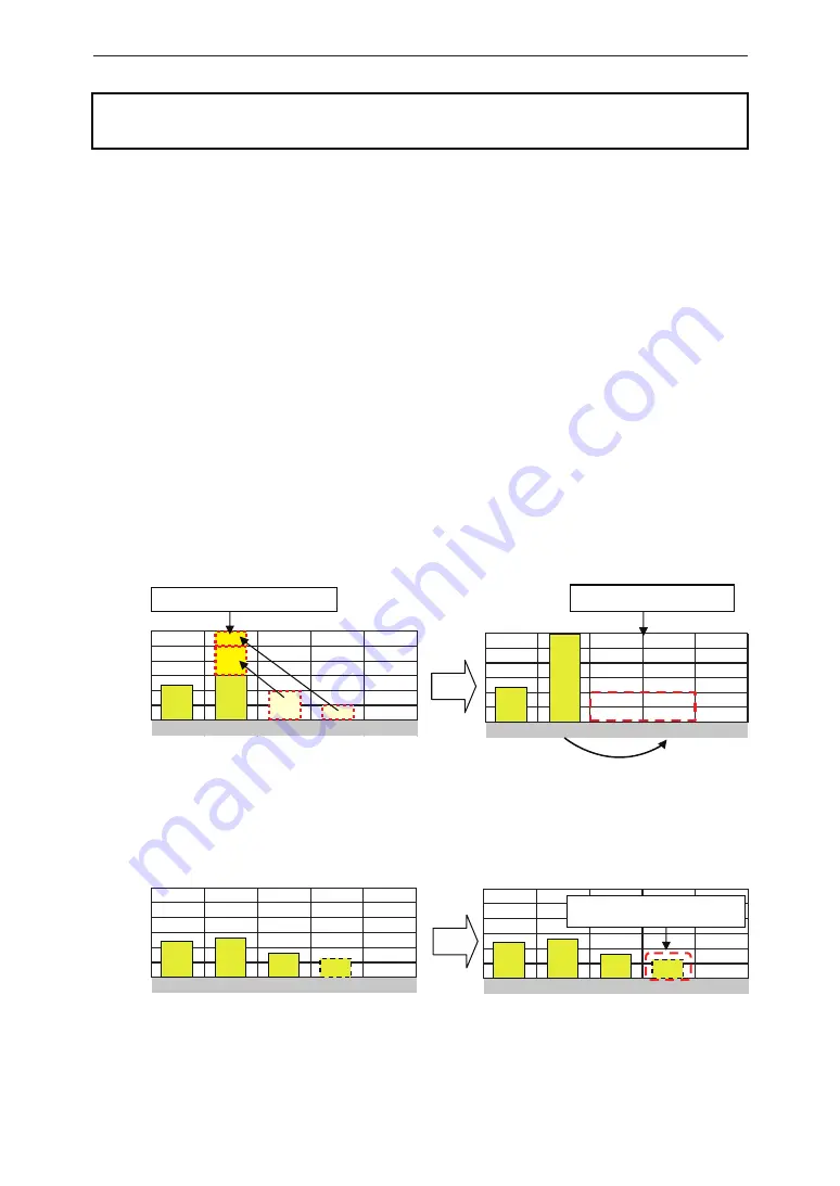
Example : [A case where performance data is lost]

The time is inadvertently changed from 9:15 to 8:45 and then reverted to 9:15.

The performance data starting from 8:45 onwards are added to the performance data from 8:45

and the performance data for the period since 8:45 is lost. Lost data cannot be restored.

● Time is changed from 9:15 to 8:45.


● 

Time is changed from 8:45 to 9:15.

Example : [A case where performance data is not lost]

The time is inadvertently changed from 9:28 to 9:18 and then reverted to 9:28. 

The performance data from 9:15 is fixed as of 9:30 and as such, the performance data is not lost,

as long as the time change does not extend to at least a 15 minute interval.

 Time is changed from 9:28 to 9:18.


● 

Time is changed from 9:18 to 9:28.

8:30    8:45    9:00    9:15    9:30

Data is added to that of 8:45.

Performance data is not lost.

Performance data is lost.

8:30    8:45    9:00    9:15    9:30

8:30    8:45    9:00    9:15    9:30

8:30    8:45    9:00    9:15    9:30

Introduction

Содержание R3E

Страница 1: ...The power behind competitiveness Delta Power Monitor Installation Manual R3E for commercial use only www deltaww com...

Страница 2: ...Communications Unit Setting Power Monitor and Cable Default Settings Connection Installation Method Wall Installation Desktop Installation Wiring access Description of the screen display Home Screen O...

Страница 3: ...d in some cases may also result in serious injury or death Failing to handle the Product properly may result in the described danger leading to slight or intermediate level injuries or property damage...

Страница 4: ...Product in the following types of locations There is danger of burnout in some rare cases Locations that are exposed to rain water such as outdoors or under eaves and the like Locations that are expos...

Страница 5: ...t is prevented from having air flow such as inside closets or under stairs 4 Install the Product with the DELTA logo facing up when installing the Power Monitor on a wall When not installed on a wall...

Страница 6: ...terval into the past will result in the loss of performance data Set the date and time correctly Example A case where performance data is lost The time is inadvertently changed from 9 15 to 8 45 and t...

Страница 7: ...ng the operating temperature range 20 to 50 C Do not install above 2000m MSL or higher Do not expose to water vapor oil vapor smoke cotton dust metal powder sawdust Warakuzu 7 Store the Product in a l...

Страница 8: ...e 2 pieces Product name Power Monitor Wall Surface Desktop Mounting Plate Wood screws for Wall Surface Desktop Mounting Plate dia 4 x 20 mm Shape Qty Remarks This is a plate used to install the Produc...

Страница 9: ...9 190mm 120mm 32mm 25mm 35mm 58mm 40mm 7 inch Power Monitor Wall Surface Desktop Mounting Plate POWER MONITOR 1 2 Dimension Preparation before construction...

Страница 10: ...ed to procure their own USB memory and USB cable Insertion slot for anchoring the Wall Surface Mounting Plate This is the insertion slot used to install the Wall Surface Desktop Mounting Plate when in...

Страница 11: ...tion 2 1 Installation order Setting One Point Please set connection ID before connect to the Inverters The ID of inverters must be different The ID range is 1 32 Default Settings Installation Method I...

Страница 12: ...odel please check the inverter Operation and Installation Manuals PV Panel Inverter Inverter 2 Inverter 3 Power Monitor Communication connector Communication connector Distribution box Switchboard The...

Страница 13: ...ave been inserted securely Cables Make sure to use RS 485 cables Prepare 0 3 to 0 5mm2 x single wire 4 cores twin wires rather than 2 pair shielded cables rated temperature 80 C to 85 C Read the inver...

Страница 14: ...e range of Power Monitor is 10Vdc 16Vdc and rated operating voltage is 12Vdc Distance limitation The power line between monitor and inverter is max 100m and the communication line between monitor and...

Страница 15: ...in connector into the main unit Pass a screwdriver through the screw hole and tighten the two screws for the 6 pin connector When all the wiring is complete install the Power Monitor in its installati...

Страница 16: ...fault Settings 4 1 Connection connection setting start screen Time settings screen Date and time shown are examples After started up please choose language Language selection screen When monitor shows...

Страница 17: ...ation dialog box will be displayed Touch the Yes button once again Time change dialog box Time change confirmation dialog box 17 Select the date frame The date selection screen will be displayed Selec...

Страница 18: ...ed immediately after the settings are made a icon is displayed so check the following details 1 to 3 mins later Check that the icon is not displayed on the home screen Check that the values for the po...

Страница 19: ...location where the provided wood screws cannot be used Apply torque of 1 5 to 2 0 Nm when installing wood screws on a wall made of wooden materials Install on a flat wall surface Verify the hooking po...

Страница 20: ...ccess Remove the tab on the wiring access using a pair of pliers or the similar tool Remove burr with a pair of pliers to ensure that the cables are not scratched Pass a screwdriver through the screw...

Страница 21: ...cessful Internet time synchronization is successful Suppression icon A Suppression icon is displayed when there is suppression on the operation of the Inverter Icon Operating mode Voltage elevation su...

Страница 22: ...or icon An error icon is displayed to indicate that one or more errors are occurring The Error icon is ordinarily not displayed and is displayed when one or more errors occur Refer to 8 When Something...

Страница 23: ...Thus the numerical values that are displayed do not necessarily completely match with the true value in some cases as described above Refer to 8 When Something Seems Wrong Troubleshooting Page 40 for...

Страница 24: ...the Inverter are unable to communicate with each other Screens indicated with solid lines are displayed for ordinary operations The screens in gray are displayed when operating in service mode Power t...

Страница 25: ...object with a slender tip into the reset hole on the base of the unit to push the reset button The device will be reset Restart the Power Monitor The settings and records will not be deleted 25 POWER...

Страница 26: ...ce Mode Service mode is a hidden mode for installer Please do not tell any customer the procedure of entering service mode Touch the home screen in the following order to enter service mode Procedure...

Страница 27: ...ecessary to switch to service mode to make the connection setting The connection setting page is not displayed in normal mode Expanding the inverters If expanding the solar generator system and adding...

Страница 28: ...amount of power generated by the additional inverters cannot be measured unless the following settings are made 1 Reset and clear all the inverter data See the inverter Operation and Installation Man...

Страница 29: ...h the button to display the inverter selection dialog box and then touch the number of the inverter that you want to view Updates the settings for the selected inverter Updates the settings for all th...

Страница 30: ...frame for the time The time selection screen will be displayed Select the time that you want to set Touch the button on the time selection screen The time change dialog box will be displayed Check the...

Страница 31: ...nchronization Time Zone Choose time zone Period Choose interval between each time synchronization The time change dialog box will disappear and the time change confirmation dialog box will be displaye...

Страница 32: ...occurring the screen is turned on and the display reverts to the Home screen Screen Brightness The brightness of the screen can be selected in ten levels Setting range 1 2 3 4 5 6 7 8 9 10 The defaul...

Страница 33: ...ed None of the settings will change until the Save button is touched at the end Caution is required Touch to turn off the dialog box Screen Change dialog box Touch and then on the home screen Operatin...

Страница 34: ...Other Devices Pyrheliometer Thermometer can be set on this page Touch and choose DEA485 to enable pyrheliometer thermometer ID range is 41 50 Touch to set and touch to close dialog 34 Service Mode...

Страница 35: ...manual of devices before setting and ask manufacturer if any question Modbus Sensor Box Pyrheliometer thermometer RS 485 Connection example Power Monitor 6 pin Connector Communications Connector Termi...

Страница 36: ...o the Power Monitor Not displayed in normal mode For maintenance by Delta For maintenance by Delta You can back up the data of the Power Monitor to USB Restores the backup data from USB to the Power M...

Страница 37: ...on page is unnecessary to set It is used to connect other devices by Ethernet Internet setting for the Power Monitor Need some knowledge of network management to setting are protocols for other indust...

Страница 38: ...nes the number of bits is used in the network address from the IP address header Gateway IP Set gateway device IP to access internet DNS Domain Name Server which manages the corresponding relationship...

Страница 39: ...ppression screen Change the display to the previous month Change the display to the next month Suppression record That displays the set of suppression details Touch on the desired date to display the...

Страница 40: ...Operating mode Description Error icon An error icon is displayed to indicate that one or more errors are occurring The Error icon is ordinarily not displayed and displayed when one or more errors occu...

Страница 41: ...when the system is not restored for a long period of time Suppression icon Displayed when the Inverter is being suppressed Icon Operating mode Voltage elevation suppression Temperature elevation supp...

Страница 42: ...should be taken in cases where the following symptoms occur are described Voltage elevation suppression and temperature elevation suppression are displayed Verify the frequency and duration of occurr...

Страница 43: ...ns 120 H x 190 W x 32 D mm Weight 440 g Displayed details Power generation calendar history Inverter information error log De rating Log display and the like Maximum power consumption 10 W or less inc...

Страница 44: ......

Страница 45: ......

Страница 46: ......

Страница 47: ......

Страница 48: ...20170113...

Отзывы: