background image

209499 Rev. A

www. s p e c s e l e c t . c o m

Page 9

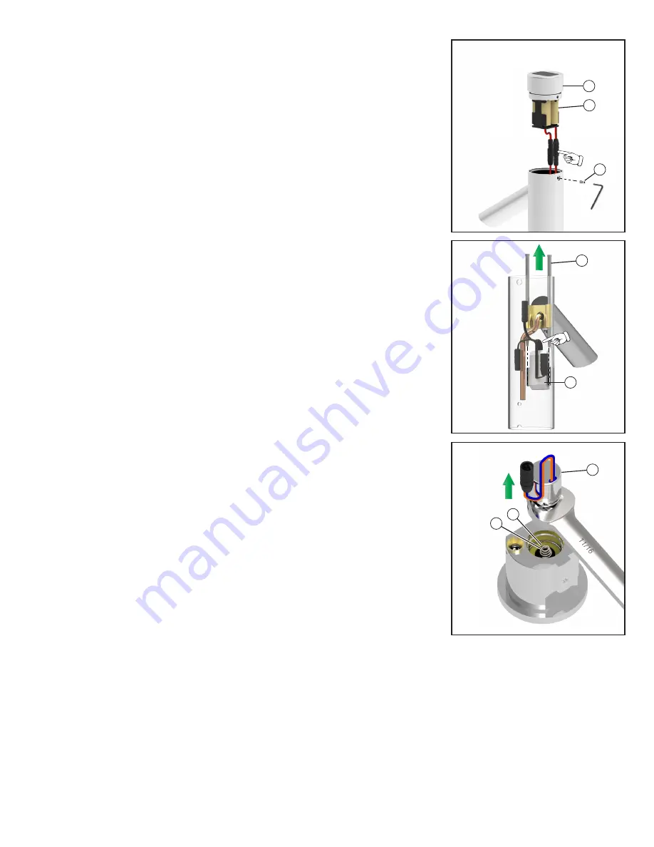
Replacing the sensor assembly (061330A) 

(see Figures 10 - 14)

1. 

Shut off the water at the supply stop(s).

2.  Activate the faucet to relieve water pressure built up within the faucet.
3.  DEMD-321LF only: Remove the side mixer handle (1) by pulling out the red/blue temperature indicator 

plug (2) and handle screw (3).

4. 

Remove the set screw (4) at the back of the faucet near the base, lift the body assembly off the faucet base 

and disconnect the solenoid.

5. 

Remove the set screw (12) holding the solar cap (10) to the body assembly. Lift off the solar cap (10) and 

battery pack (11) and disconnect them from the sensor.

6.  There are two stainless steel locking pins (13) in the faucet that secure the sensor assembly (14). Pull out 

the stainless steel pins up through the top of the faucet. It may be necessary to push the pins up from the 

bottom of the faucet.

7.  Replace the sensor assembly. 

Note: 

The sensor must be oriented with the wires going upwards.

8.  Reinstall the locking pins (13).
9.  Reconnect the solenoid cable.
10.  There is a copper tube (9) in the body assembly that must be aligned to the outlet port (8) in the faucet base 

so the body assembly can fit back over the faucet base.

11.  Lock the faucet base to the body assembly using the set screw (4).
12.  Reconnect the battery pack (11) and reinstall the solar cap (10) with set screw (12).
13.  DEMD-321LF only: Reassemble the handle (1) and red/blue temperature indicator plug (2).

Note: 

The temperature indicator plug should be oriented with the blue on the left and red on the right.

14.  Restore water by opening the supply stop(s).
15.  Activate faucet several times and check for leaks

Replacing the solenoid assembly (061328A) 

(see Figures 10 - 12 & 15)

1. 

Shut off the water at the supply stop(s).

2.  Activate the faucet to relieve water pressure built up within the faucet.
3.  DEMD-321LF only: Remove the side mixer handle (1) by pulling out the red/blue temperature indicator 

plug (2) and handle screw (3).

4. 

Remove the set screw (4) at the back of the faucet near the base, lift the body assembly off the faucet base 

and disconnect the solenoid.

5.  Use a 11/16” or 17mm wrench (1/4” thick max) to remove the solenoid assembly (15) from the faucet base. 

Remove the diaphragm (16) and spring (17) if they are still in the faucet base.

6.  Replace the solenoid assembly
7.  Reconnect the solenoid cable.
8.  There is a copper tube (9) in the body assembly that must be aligned to the outlet port (8) in the faucet base 

so the body assembly can fit back over the faucet base.

9.  Lock the faucet base to the body assembly using the set screw (4).
10.  Reassemble the handle (1) and red/blue temperature indicator plug (2). 

Note: 

The temperature indicator plug (2) should be oriented with blue on the left and red on the right.

11.  Restore water by opening the supply stop(s).
12.  Activate faucet several times and check for leaks.

12

Fig. 13

10

11

Fig. 14

14

13

Fig. 15

15

17

16

Содержание DEMD-320LF

Страница 1: ...automatique Apagado autom tico 30 seconds 30 secondes 30 segundos Preset sensor range Port e pr r gl e du capteur Rango del sensor preajustado 6 8 153 mm 203 mm 6 po 8 po 153 mm 203 mm 6 8 153 mm 203...

Страница 2: ...lules solaires Mecanismo de celdas solares 061327A Battery Holder Support de la pile Contenedor de bater a DEMD 321LF DEMD 320LF 061330A Sensor Assembly Ensemble du capteur Ensemble du capteur 061328A...

Страница 3: ...de reflet il est recommand de maintenir une distance minimale de 6 pi 2 m 1 5 m tre entre le robinet et d autres objets Pr paration pour l installation Purgez les conduites d eau avant d installer le...

Страница 4: ...que les languettes d alignement soient correctement orient es 3 Ins rez le support de batterie 2 dans le capuchon solaire 1 de la fa on indiqu e Figure 2 avec le c t ouvert du support de pile 2 align...

Страница 5: ...l paso 1 3 Si el problema persiste consulte la gu a de resoluci n de problemas al final de este documento Step 3 Install faucet onto the sink see Figures 4 5 1 Remove lock nuts 8 and set aside 2 Pass...

Страница 6: ...u voir les Figures 6 et 7 1 Installez les assemblages de filtre en ligne 10 sur les vannes d arr t 2 Raccordez les tuyaux d alimentation 9 aux filtres en ligne 10 Remarque Pour le DEMD 321LF raccordez...

Страница 7: ...una mano delante del sensor hasta que se haya purgado todo el aire de las l neas de suministro 3 Verifique que no tenga fugas 4 Cierre las llaves de paso del agua antes de instalar el aireador 11 util...

Страница 8: ...aerator under running water to remove debris 5 Reassemble the aerator to the faucet Ensure the aerator washer is installed properly 6 Restore water by opening the supply stop s 7 Activate faucet seve...

Страница 9: ...with set screw 12 13 DEMD 321LF only Reassemble the handle 1 and red blue temperature indicator plug 2 Note The temperature indicator plug should be oriented with the blue on the left and red on the r...

Страница 10: ...eur sous de l eau courante pour enlever les d bris 5 Remontez l a rateur sur le robinet Assurez vous que la rondelle de l a rateur soit install e correctement 6 Restaurez l alimentation en eau en ouvr...

Страница 11: ...ntez la poign e 1 et la fiche de l indicateur de temp rature rouge bleu 2 Remarque La fiche de l indicateur de temp rature 2 doit tre orient e avec le bleu gauche et rouge droite 14 Restaurez l alimen...

Страница 12: ...lave Verifique que la arandela del aireador est colocada correctamente 6 Vuelva a abrir las llaves de paso del agua 7 Active la llave varias veces y verifique que no tenga fugas Instrucciones de limpi...

Страница 13: ...12 13 Solamente para DEMD 321LF Vuelva a armar el mango 1 y el tap n rojo azul indicador de temperatura 2 Nota El tap n indicador de temperatura debe quedar orientado con el lado azul hacia la izquier...

Страница 14: ...ge Debris in diaphragm Replace the solenoid refer to Maintenance instructions on Replacing the solenoid assembly 061328A on page 9 Diaphragm is torn Replace solenoid refer to Maintenance instructions...

Страница 15: ...vous aux directives Entretien dans Remplacez le sol no de 061328A voir Figures 10 12 et 15 on page 11 La membrane est d chir e Remplacez le sol no de reportez vous aux instructions Entretien dans Rem...

Страница 16: ...ura 10 12 y 15 on page 13 El diafragma est roto Reemplace el solenoide consulte las instrucciones de Mantenimiento dentro de Reemplazo del mecanismo del solenoide 061328A ver Figura 10 12 y 15 on page...

Страница 17: ...elta risquent d annuler le droit de l utilisateur utiliser l quipement CAN ICES 3 A NMB 3 A 2017 Masco Canada Lte Pour obtenir de l assistance technique appelez le Service Technique de Delta Commercia...

Страница 18: ...NADOS EST N EXCLUIDOS Y NO SER N CUBIERTOS POR DELTA FAUCET Algunos estados provincias no permiten limitaciones con respecto a cu nto dura una garant a impl cita o la exclusi n o limitaci n de da os i...

Отзывы: