17- ENG
D27449
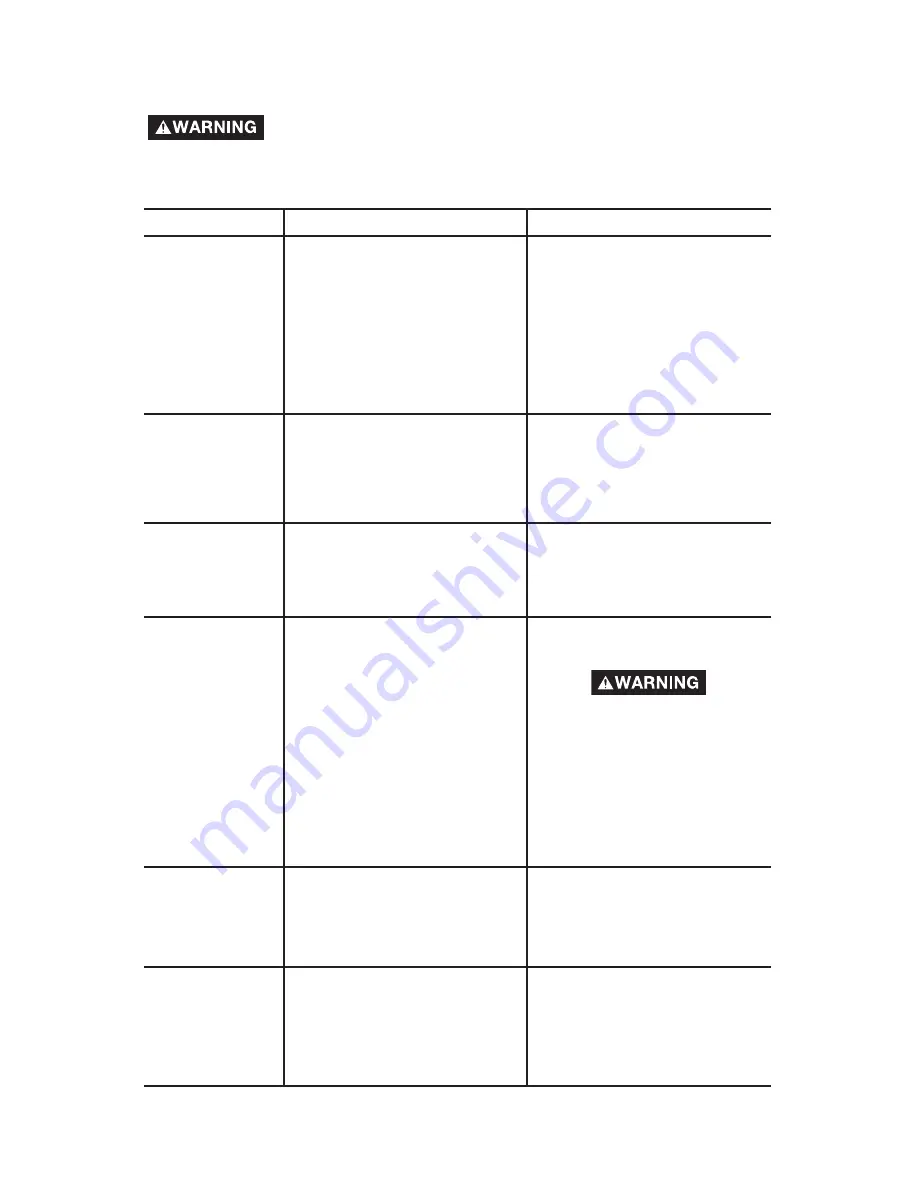
Performing repairs may expose voltage sources, moving
parts or compressed air sources, moving parts or
compressed air sources. Personal injury may occur. Prior to attempting
any repairs, unplug the air compressor and bleed off all air tank air
pressure.
PROBLEM
CAUSE
CORRECTION
Pressure switch does not
shut off motor when
compressor reaches “cut-
out” pressure.
Pressure switch “cut-out”
too high.
Move On/Auto/Off lever to
the “OFF” position, if the
outfit does not shut off
contact a Trained Service
Technician.
Contact a Trained Service
Technician.
Excessive tank
pressure - safety
valve pops off.
Tube fittings are not tight
enough.
Tighten fittings where air can
be heard escaping. Check
fittings with soapy water
solution.
Do Not
Overtighten.
Air leaks at
fittings.
Air leaks at
pressure switch
release valve.
(if equipped)
Defective pressure switch
release valve.
Contact a Trained Service
Technician.
Air leaks in air
tank or at air
tank welds.
Defective air tank.
Air tank must be replaced.
Do not repair the leak.
Do not drill into, weld or
otherwise modify air tank
or it will weaken. The tank
can rupture or explode.
Air leaks
between head
and valve plate.
Leaking seal.
Contact a Trained Service
Technician.
Possible defect in safety
valve.
Operate safety valve manually
by pulling on ring. If valve
still leaks, it should be
replaced.
Air leak from
safety valve.
Possible defect in safety
valve.
Operate safety valve manually
by pulling on ring. If valve still
leaks, it should be replaced.
Knocking Noise.
TROUBLESHOOTING
Содержание 66-500-1
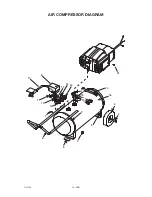
Страница 20: ...20 ENG D27449 AIR COMPRESSOR DIAGRAM 21 5 13 16 4 3 9 10 1 11 15 6 14 12 8 7 7 17 20 18 19 2 ...
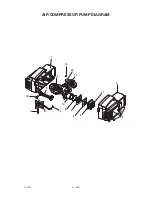
Страница 22: ...22 ENG D27449 AIR COMPRESSOR PUMP DIAGRAM 1 15 20 14 16 9 12 7 4 10 11 13 8 6 5 3 21 2 18 ...
Страница 44: ...44 SP D27449 DIAGRAMA DEL COMPRESOR DE AIR 21 5 13 16 4 3 9 10 1 11 15 6 14 12 8 7 7 17 20 18 19 2 ...
Страница 46: ...46 SP D27449 DIAGRAMA DE LA BOMBA DEL COMPRESOR 1 15 20 14 16 9 12 7 4 10 11 13 8 6 5 3 21 2 18 ...
Страница 68: ...68 FR D27449 DIAGRAMME DU COMPRESSEUR À AIR 21 5 13 16 4 3 9 10 1 11 15 6 14 12 8 7 7 17 20 18 19 2 ...
Страница 70: ...70 FR D27449 DIAGRAMME DU POMPE 1 15 20 14 16 9 12 7 4 10 11 13 8 6 5 3 21 2 18 ...

