background image

Page 3

212294   Rev. 

B

w w w . s p e c s e l e c t . c o m

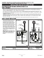
FOR RECESS MOUNT HOUSING: CONTROL BOXES #1 & 8


INSTALLATION AND SET UP INSTRUCTIONS

Installation should be in accordance with local plumbing and electrical codes.

FLUSH ALL PIPES THOROUGHLY BEFORE INSTALLATION. 

COVERS

060073A

Screws (4/pkg) and driver bit for covers

060577A

12” Stainless Steel Cover

TMV Repair Kits

061137A

Adjustment Wrench

STEP 1. ROUGH IN

STEP 2. FAUCET INSTALLATION


Note:

 Wires connecting between box(es) and from transformer must be protected from abrasion, and being pulled at connections.  They

also may have to be fished through at a later stage of construction.  Depending on installation, the cable bushings included may be

replaced by 

installer supplied

 1/2” conduit.  Rough-in box as per Figure 8.

The transformer is to be installed in an adjacent accessible space.  (

Do NOT install the transformer inside the control box.)

  Cable

from the transformer to the driver board/controller may be roughed in at this time depending on installation.  Use cable which complies to

local electrical codes for a 1 amp load.

HARDWIRE OR BATTERY

:


 If recessed box is supplied, rough in as per Figure 8.  The most vandal resistant installation is when the

control box is as close to the bottom of the sink as feasible.  For wall hung sink installation, sensor conduit rough in should be directly

under the basin to minimize sensor cord exposure.  Rough in drainage.  Rough in water supply to 10” control box inlets and to spout

connection.  Finish walls.
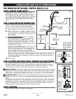
Valve spacer is for temporary use only for flushing of system. Must be replaced with solenoid valve and washers (Fig. 6 & 7).

Clean deck/sink surface where faucet will

be mounted.  Mount faucet to sink using

nut(s) and washer(s) provided (Fig. 1).

Installation of the deck gasket (061031A)

between the fixture and mounting surface

is the recommended assembly practice.

Ensure that gasket is sitting flat on the deck

and the fixture is centered on the gasket.

Mount the faucet to the sink using nut(s)

and washer(s) provided (RP6001).  Tighten

both nuts equally.  Do not overtighten the

nut or reposition the fixture once installed,

otherwise damage to the gasket may result.

Cutting or trimming of the gasket is not

recommended.

NOTE: If the gasket is trimmed or not

installed, then use clear silicone sealant

between the faucet and lavatory to

prevent water from leaking beneath

lavatory.

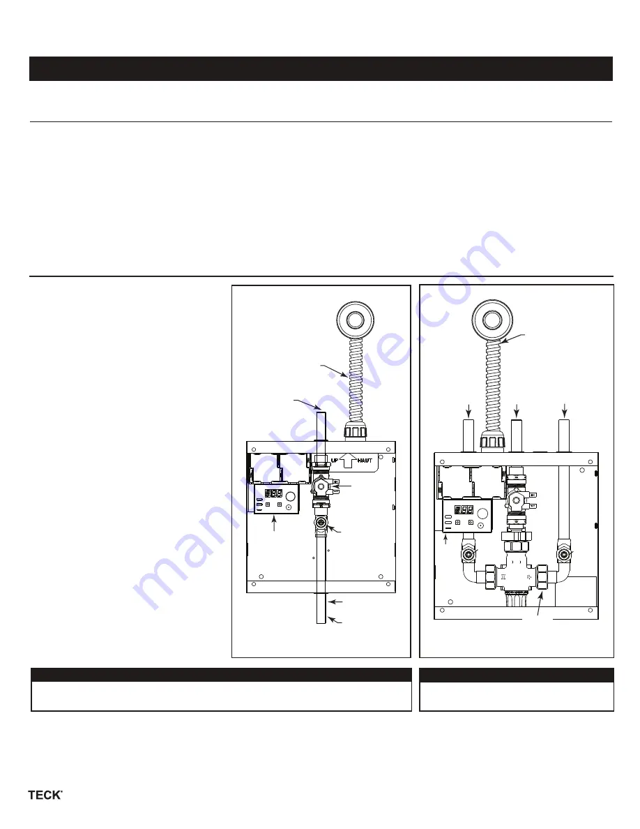
Control Box #1

Fig. 6

Control Box #8

Fig. 7

Tempered Water

(By Others) 

Inlet:

1/2” Sweat

060671A

3/4” NPS

Solenoid

Valve &

Washers

061252A

Driver board

to be located

on bracket

063135A

Stop Kit

1/2” Sweat

Outlet

061252A

Driver

board

to be

located

on

bracket

063135A

Stop Kit

063135A

Stop Kit 

Hot Inlet

1/2” Sweat

1/2” Sweat

Outlet

Cold Inlet

1/2” Sweat

063179A

Thermostatic Mixing Valve

with checks & gaskets 

Flexible Sensor

Cord Conduit

(supplied on Recessed

Mount Box)

Flexible Sensor

Cord Conduit

(supplied on

Recessed Mount Box)

063164A

Check Valves (2/pkg)

Содержание 591T Series

Страница 1: ... L min 061203A Vandal Resistant Laminar Outlet with Wrench 0 5 GPM 1 9 L min 061176A Vandal Resistant Laminar Outlet with Wrench 1 0 GPM 3 8 L min 061104A Vandal Resistant Flow Control Non Aerating Spray Outlet with Wrench 0 35 USGPM 1 3 L min RP31704 Optional Vandal Resistant Spray Outlet with Wrench 0 5 GPM 1 9 L min 060566A Optional Vandal Resistant Spray Outlet with Wrench 1 0 GPM 3 8 L min RP...

Страница 2: ...tly inside the battery box Do not remove battery snap from hardwire converter by using a flat screwdriver damage may result Turn on power supply for the transformer STEP 6 PREPARE SINK AREA Before connecting the spout cable clean off counter and remove all objects from the sink STEP 7 TIE SPOUT CABLE Attach spout cable to box connector Use tie wraps to secure spout cable to spout hose Your faucet ...

Страница 3: ...asin to minimize sensor cord exposure Rough in drainage Rough in water supply to 10 control box inlets and to spout connection Finish walls Valve spacer is for temporary use only for flushing of system Must be replaced with solenoid valve and washers Fig 6 7 Clean deck sink surface where faucet will be mounted Mount faucet to sink using nut s and washer s provided Fig 1 Installation of the deck ga...

Страница 4: ...the temperature is more than 3 F from the commissioning in temperature refer to the included Cash Acme Maintenance and Installation Guide 4D Close stop s STEP 5 CONNECT ELECTRICAL SUPPLY SOLENOID VALVE AND SENSOR Remove plastic threaded spacer nipple and install solenoid valve with body arrow in the direction of water flow See Fig 10 Feed sensor wire from spout into control box and then connect to...

Страница 5: ...to 15 from sensor 5 7 10 12 15 30 45 60 75 90 seconds 2 0 4 0 6 0 8 0 9 9 minutes Symbol d T R Rinse Cycle If this feature is turned to an xx hour value the faucet will turn on itself after this set time from last use OFF 6 12 18 24 30 36 42 48 hours r Rinse Time This is the amount of time you want the faucet to stay on to move the water in the line if the Rinse Cycle is made active 10 seconds onc...

Страница 6: ...e default setting is OFF METERING MODE M This feature changes the product into a metering faucet it will run the full set amount of time after the user s hands are first detected and will continue to run after the user removes their hands Options are OFF 7 8 9 10 11 12 13 14 15 18 24 30 40 50 60 90 seconds and 2 0 2 5 3 0 3 5 4 0 minutes decimal denotes minutes The default setting is OFF Note Auto...

Страница 7: ...ce Hard Wire converter 060683A if required The faucet stops working No water flow Check the function of the solenoid Step 3 The solenoid should click when activated Clean as required Correct as required If there is a clicking sound If no clicking sound This indicates that both the sensor and the solenoid are functioning Ensure inlet screen on solenoid is not plugged with debris Check the incoming ...

Страница 8: ...NTIAL SPECIAL INDIRECT OR PUNITIVE DAMAGES CONNECTED THEREWITH ARE EXCLUDED AND WILL NOT BE PAID BY DELTA FAUCET Some states provinces do not allow limitations on how long an implied warranty lasts or the exclusion or limitation of incidental or consequential damages so the above limitations or exclusions may not apply to you This warranty gives you specific legal rights and you may also have othe...

Отзывы: