background image

4

Fig. 2

UNPACKING AND CLEANING

Carefully unpack the tool and all loose items from the shipping container(s). Remove the protective coating from all
unpainted surfaces. This coating may be removed with a soft cloth moistened with kerosene (do not use acetone, gasoline
or lacquer thinner for this purpose). After cleaning, cover the unpainted surfaces with a good quality household floor paste
wax.

1.

Motor and blower assembly

2.

Base

3.

Wheel casters (4)

4.

Side support (2)

5.

Upper bag (bag with loop see Fig. 14)

6.

Lower bag

7.

Filter bag clamp (2)

8.

Firm board

9.

Filter bag hanger

10. Hose
11. Hose clamp (2)
12. 5/16 Hex nut (9)
13. 5/16 Lockwasher (12)
14. 5/16-18x3/4" Hex head screw (12)
15. Intake cap

1

2

3

4

5

6

7

8

9

10

11

12

13

14

15

Содержание 50-775

Страница 1: ...l 50 775 PART NO 902116 015 Copyright 2001 Delta Machinery To learn more about DELTA MACHINERY visit our website at www deltamachinery com For Parts Service Warranty or other Assistance please call 1...

Страница 2: ...y to get caught in moving parts Nonslip footwear is recommended Wear protective hair covering to contain long hair 12 SECURE WORK Use clamps or a vise to hold work when practical It s safer than using...

Страница 3: ...with sharp edges hot surfaces oil or grease Do not place anything over the top of the power cord 9 DO NOT unplug the dust collector by pulling on the power cord DO NOT place anything over the top of t...

Страница 4: ...gasoline or lacquer thinner for this purpose After cleaning cover the unpainted surfaces with a good quality household floor paste wax 1 Motor and blower assembly 2 Base 3 Wheel casters 4 4 Side suppo...

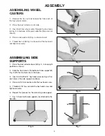
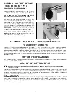
Страница 5: ...en securely Fig 3 Fig 4 ASSEMBLING SIDE SUPPORTS 1 Place the dust collector base A Fig 5 in an upright position as shown 2 Align the two holes in the bottom of side support B Fig 5 with the two holes...

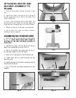
Страница 6: ...ached to the side supports Fig 8 Fig 9 ASSEMBLING FIRM BOARD 1 Place the firm board A inside the two side supports B Fig 10 NOTE MAKE SURE FIRM BOARD IS ATTACHED TO THE SIDE SUPPORTS CLOSEST TO THE MO...

Страница 7: ...essary to adjust the height of the drum support rod at this time If adjustment is necessary loosen nut A Fig 13 and rotate support rod B as needed to obtain proper rod height to support filter bag F T...

Страница 8: ...which accept the tool s plug Before connecting the motor to the power line make sure the switch is in the OFF position and be sure that the electric current is of the same characteristics as indicated...

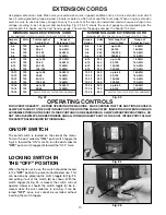
Страница 9: ...ver the adapter is used it must be held in place with a metal screw 240 VOLT SINGLE PHASE OPERATION The motor supplied with your tool is a dual voltage 120 240 volt motor The dust collector motor is s...

Страница 10: ...240 50 100 16 AWG 0 6 240 100 200 16 AWG 0 6 240 200 300 14 AWG 6 10 240 up to 50 18 AWG 6 10 240 50 100 16 AWG 6 10 240 100 200 14 AWG 6 10 240 200 300 12 AWG 10 12 240 up to 50 16 AWG 10 12 240 50 1...

Страница 11: ...inate potential cord damage MOTOR MAINTENANCE Removing dust and dirt Blow off motor with low pressure air to remove dust or dirt Air pressure above 50 P S I should not be used as high pressure may dam...

Страница 12: ...12 NOTES...

Отзывы: