background image

9

HEADSTOCK SPUR CENTER

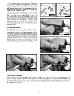
The 46-715 comes with a faceplate attached. Before inserting the spur center in the spindle,
remove this faceplate. Insert the knockout bar (A) Fig. 10 in the side hole of the spindle (B)
Fig. 10 to hold the spindle in place. Use the supplied wrench (C) Fig. 10 to loosen the
faceplate. Remove the faceplate (D) by turning it counter-clockwise with your hand. The
spur center (A) Fig.11 is equipped with a No. 2 Morse Taper shank. Insert this shank into the
headstock spindle (B). 

NOTE: 

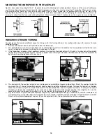
Before inserting the spur center (A), clean both the shank of the spur center and the

inside of the headstock spindle to remove any grease or debris. To remove the tapered
shank spur center (A) Fig. 11 from the headstock spindle (B) Fig. 11, use the knockout bar
(C) Fig. 12 through the hole (D) in the opposite end of the spindle to push the spur center
out. 

IMPORTANT: Never drive the workpiece into the spur center when it is mounted in the
headstock.

See instructions on setting the spur center into the workpiece in the 

“OPERATION“ 

section

of this manual under “

CENTERING THE WORK

.”

Fig. 10

Fig. 11

Fig. 12

Fig. 13

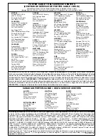
TAILSTOCK LIVE CENTER

The tailstock live center (A) Fig. 13, supplied with your lathe, is equipped with a No. 2 Morse Taper shank. 

NOTE:

Before inserting the live center, clean both the shank and the inside of the tailstock to remove any grease or debris. To remove

the live center (A) from the tailstock spindle (B), use the knockout bar (C) Fig. 12 (supplied) through the hole (D) in the opposite end
of the spindle.

D

C

B

A

B

A

A

B

B

A

C

D

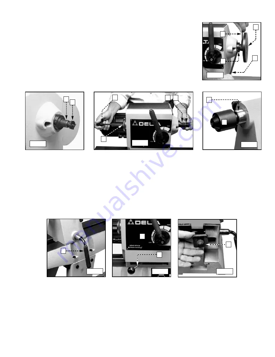
ADJUSTING CLAMPS ON THE HEADSTOCK AND TAILSTOCK

The headstock and tailstock can be moved along the lathe bed. A downward push on the handle (A) Fig. 14 locks the mechanism,
while an upward movement of the handle releases the securing action. The clamps are pre-set at the factory. However, should either
need adjusting, use an 11/16” wrench to slightly loosen or tighten the nut (A) Fig. 16 on the tailstock. 

NOTE:

Clamp the headstock and tailstock firmly while operating the lathe.

Fig. 14

Fig. 15

Fig. 16

A

A

B

A

TOOL REST

The tool rest (A) and tool rest base (B) are shown in Fig. 17. To position the tool rest on the lathe bed, lift the clamp handle (C), move
the tool rest base and lock it in place by pushing down on the handle (C). To adjust the tool rest (A) for the correct height, loosen
the locking lever (D), move the tool rest (A) up or down and tighten the locking lever (D).

NOTE:

The locking lever (D) Fig. 17 can be positioned on the left or right side of the tool rest base (B). To reposition the tool rest

locking lever (D), unscrew the lever counterclockwise. A threaded hole is provided in the left side of tool rest base (B) to accept the
locking lever (D). 

NOTE:

Clamp the tool rest firmly while operating the lathe. 

Содержание 46-715

Страница 1: ...right 2005 Delta Machinery To learn more about DELTA MACHINERY visit our website at www deltamachinery com For Parts Service Warranty or other Assistance please call 1 800 223 7278 In Canada call 1 80...

Страница 2: ...t www deltamachinery com Postal Mail Technical Service Manager Delta Machinery 4825 Highway 45 North Jackson TN 38305 Information regarding the safe and proper operation of this tool is available from...

Страница 3: ...EMS The symbols below are used to help you recognize this information SAFETY GUIDELINES DEFINITIONS SOME DUST CREATED BY POWER SANDING SAWING GRINDING DRILLING AND OTHER CONSTRUCTION ACTIVITIES contai...

Страница 4: ...to the machine and or injury may result 13 USE RECOMMENDED ACCESSORIES The use of accessories and attachments not recommended by Delta may cause damage to the machine or injury to the user 14 USE THE...

Страница 5: ...ning 19 MOVE THE CUTTING TOOL INTO THE WORKPIECE SLOWLY and cut small amounts when roughing 20 REMOVE THE TOOL REST before sanding or polishing 21 NEVER PERFORM LAYOUT assembly or set up work on the t...

Страница 6: ...ipment grounding conductor can result in risk of electric shock The conductor with insulation having an outer surface that is green with or without yellow stripes is the equipment grounding conductor...

Страница 7: ...le Wrench 11 Live Center 12 M8 x 16mm Carriage Bolts 24 13 Nuts 32 14 Flat Washers 32 15 Lockwashers 32 16 M8 x 35mm Hex Head Screws 8 17 Drive Center 1 UNPACKING AND CLEANING 2 3 4 5 8 6 7 9 10 11 12...

Страница 8: ...that secure it The headstock is very heavy Have someone help remove it from the lathe bed 3 Loosen the lock handle C Fig 5 and slide the headstock off the end of the lathe bed 4 Loosen the lock handle...

Страница 9: ...r clean both the shank and the inside of the tailstock to remove any grease or debris To remove the live center A from the tailstock spindle B use the knockout bar C Fig 12 supplied through the hole D...

Страница 10: ...with the bolts that were removed in STEP 1 Fig 20 A C D C STARTING AND STOPPING THE TOOL The power switch A Fig 22 located under the safety cover B Fig 21 provides electrical power to the adjustable s...

Страница 11: ...een grooves 2 Gouge Tool A Fig 26 used mostly for roughing cuts and cove cuts 3 Grind Bevel part of a chisel 4 Heel The bottom of the angle on a Skew chisel 5 Live center Supports the workpiece on the...

Страница 12: ...a starting seat for the spur center by sawing on the diagonal lines and drilling a small hole at the intersection After driving the center hold the center and the work together and fit both immediatel...

Страница 13: ...from left to right Left to right from headstock to tailstock is preferred since this action throws chips clear of the operator 2 Roll the gouge over slightly in the same direction that it is advancing...

Страница 14: ...ile the other hand holds the calipers in the cutting groove When parting tool cuts are deep make a clearance cut alongside the first cut Fig 40 to prevent burning the tool point SQUARING AN END You ca...

Страница 15: ...ping position If the cutting technique is used engage only with the heel of skew in a very light cut CUTTING SMALL BEADS Beads can be scraped or cut Using the spear chisel is the easiest method of scr...

Страница 16: ...point of the cutting edge is the contact point with the wood As the cut progresses toward and around the end of the curve the handle is gradually raised and swiveled to the right Fig 53 in order to ma...

Страница 17: ...IONS When the turning has a square section joint the stock before turning Good centering is essential since any error will show at the shoulder where the round meets the square Turning of the shoulder...

Страница 18: ...3 If the faceplate is already on the headstock remove it by inserting the knockout bar A Fig 66 in the side hole of the spindle B Fig 66 to hold the spindle in place Use the supplied wrench C Fig 66...

Страница 19: ...ssibly dissolve or otherwise damage the material Wear ANSI Z87 1 safety glasses while using compressed air FAILURE TO START Should your machine fail to start check to make sure the prongs on the cord...

Страница 20: ...location of the nearest service outlet please call 1 800 223 7278 In Canada call 1 800 463 3582 SERVICE 2 Use a 5 Allen wrench to remove the three screws A Fig 72 Slide the spindle handle out Pull the...

Страница 21: ...ations Please visit our Web Site www deltamachinery com for a catalog or for the name of your nearest supplier Since accessories other than those offered by Delta have not been tested with this produc...

Страница 22: ...Delta may require that electric motors be returned prepaid to a motor manufacturer s authorized station for inspection and repair or replacement Delta will not be responsible for any asserted defect...

Страница 23: ...23 NOTES...

Страница 24: ...F brica Porter Cable Delta m s cercano ARIZONA Phoenix 85013 2906 4501 N 7th Ave Phone 602 279 6414 Fax 602 279 5470 CALIFORNIA Ontario 91761 Los Angeles 3949A East Guasti Road Phone 909 390 5555 Fax...

Отзывы: