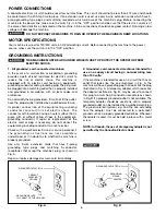
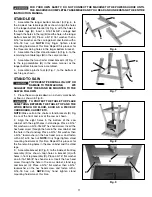
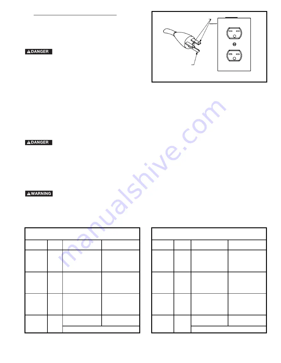
Delta 36-649 Скачать руководство пользователя страница 7

7

Fig. C

GROUNDED OUTLET BOX

CURRENT

CARRYING

PRONGS

GROUNDING BLADE
IS LONGEST OF THE 3 BLADES
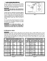
EXTENSION CORDS

Use proper extension cords. Make sure your extension cord is in good condition and is a 3-wire

extension cord which has a 3-prong grounding type plug and matching receptacle which will accept the machine’s
plug. When using an extension cord, be sure to use one heavy enough to carry the current of the machine. An
undersized cord will cause a drop in line voltage, resulting in loss of power and overheating. Fig. D-1 or D-2, shows
the correct gauge to use depending on the cord length. If in doubt, use the next heavier gauge. The smaller the gauge
number, the heavier the cord.

Fig. D-1

Fig. D-2

MINIMUM GAUGE EXTENSION CORD

RECOMMENDED SIZES FOR USE WITH STATIONARY ELECTRIC MACHINES

Ampere

Total Length

Gauge of

Rating

Volts

of Cord in Feet

Extension Cord

0-6

120

up to 25

18 AWG

0-6

120

25-50

16 AWG

0-6

120

50-100

16 AWG

0-6

120

100-150

14 AWG

6-10

120

up to 25

18 AWG

6-10

120

25-50

16 AWG

6-10

120

50-100

14 AWG

6-10

120

100-150

12 AWG      

10-12

120

up to 25

16 AWG

10-12

120

25-50

16 AWG

10-12

120

50-100

14 AWG

10-12

120

100-150

12 AWG

12-16

120

up to 25

14 AWG

12-16

120

25-50

12 AWG

12-16

120

GREATER THAN 50 FEET NOT RECOMMENDED

MINIMUM GAUGE EXTENSION CORD

RECOMMENDED SIZES FOR USE WITH STATIONARY ELECTRIC MACHINES

Ampere

Total Length

Gauge of

Rating

Volts

of Cord in Feet

Extension Cord

0-6

240

up to 50

18 AWG

0-6

240

50-100

16 AWG

0-6

240

100-200

16 AWG

0-6

240

200-300

14 AWG

6-10

240

up to 50

18 AWG

6-10

240

50-100

16 AWG

6-10

240

100-200

14 AWG

6-10

240

200-300

12 AWG      

10-12

240

up to 50

16 AWG

10-12

240

50-100

16 AWG

10-12

240

100-200

14 AWG

10-12

240

200-300

12 AWG

12-16

240

up to 50

14 AWG

12-16

240

50-100

12 AWG

12-16

240

GREATER THAN 100 FEET NOT RECOMMENDED

3.

240 VOLT SINGLE PHASE OPERATION:

The motor supplied with your saw is a dual voltage,
120/240 volt motor. If it is desired to operate your saw at
240 volts, single phase, it is necessary to reconnect the
motor leads in the motor junction box by following the
in-structions given on the motor nameplate. 

MAKE SURE MOTOR IS DISCONNECTED

FROM POWER SOURCE BEFORE RECONNECTING
MOTOR LEADS

.

It is also necessary to replace the 120 volt plug, supplied
with the motor, with a UL/CSA Listed plug suitable for
240 volts and the rated current of the saw as illustrated
in Fig. C. Contact your local Authorized Delta Service
Center or qualified electrician for proper procedures to
install the plug. The saw must comply with all local and
national electrical codes after the 240 volt plug is
installed.

The saw with a 240 volt plug should only be connected
to an outlet having the same configuration as the plug
illustrated in Fig. C. No adapter is available or should be
used with the 240 Volt plug.

IN ALL CASES, MAKE CERTAIN THE

R E C E P TA C L E I N Q U E S T I O N I S P R O P E R LY
G R O U N D E D . I F Y O U A R E N O T S U R E H AV E A
QUALIFIED ELECTRICIAN CHECK THE RECEPTACLE.

Содержание 36-649

Страница 1: ...8 36 679 PART NO 912857 8 23 04 Copyright 2004 Delta Machinery To learn more about DELTA MACHINERY visit our website at www deltamachinery com For Parts Service Warranty or other Assistance please cal...

Страница 2: ...www deltamachinery com Postal Mail Technical Service Manager Delta Machinery 4825 Highway 45 North Jackson TN 38305 Information regarding the safe and proper operation of this tool is available from...

Страница 3: ...EMS The symbols below are used to help you recognize this information SAFETY GUIDELINES DEFINITIONS SOME DUST CREATED BY POWER SANDING SAWING GRINDING DRILLING AND OTHER CONSTRUCTION ACTIVITIES contai...

Страница 4: ...a machine or an attachment to do a job for which it was not designed Damage to the machine and or injury may result 13 USE RECOMMENDED ACCESSORIES The use of accessories and attachments not recommend...

Страница 5: ...ece between the fence and a moulding cutterhead 10 CUTTING THE WORKPIECE WITHOUT THE USE OF A FENCE OR MITER GAUGE IS KNOWN AS FREEHAND CUTTING NEVER perform free hand operations Use either the fence...

Страница 6: ...unded outlet box Whenever the adapter is used it must be held in place with a metal screw NOTE In Canada the use of a temporary adapter is not permitted by the Canadian Electric Code 1 All grounded co...

Страница 7: ...f Rating Volts of Cord in Feet Extension Cord 0 6 240 up to 50 18 AWG 0 6 240 50 100 16 AWG 0 6 240 100 200 16 AWG 0 6 240 200 300 14 AWG 6 10 240 up to 50 18 AWG 6 10 240 50 100 16 AWG 6 10 240 100 2...

Страница 8: ...dwheel 2 7 Miter Gage Handle 8 Motor Plate 9 Motor Pulley 10 Miter Gage Body 11 Miter Gage Guide Bar 12 Splitter Bracket 13 Blade Guard and Splitter Assembly 14 Saw Blade 15 7 8 Open End Wrench 16 7 8...

Страница 9: ...L 36 649 2 SHEET METAL EXTENSION WINGS MODEL 36 678 1 CAST IRON EXTENSION WING MODEL 36 679 2 CAST IRON EXTENSION WINGS STAND PARTS 1 Leg 4 2 Bracket 24 Long 2 3 Bracket 21 Long 2 4 Top Bracket 1 5 Pl...

Страница 10: ...Hex Nut 1 23 1 4 20 Wing Nut 1 24 Spacer 1 25 Pin 2 26 Spring 1 27 Motor Pulley Key 1 1 2 3 4 5 6 8 9 10 11 12 14 16 17 18 20 22 23 24 25 26 7 13 19 27 15 21 UNPACKING AND CLEANING Carefully unpack th...

Страница 11: ...HE MACHINE WE SUGGEST THAT THE STAND BE MOUNTED TO THE SAW AS FOLLOWS 1 Place the saw upside down on a sturdy work bench or floor as shown in Fig 8 TO PROTECT THE TABLE TOP PLACE SOMETHING BETWEEN THE...

Страница 12: ...rmly tighten all stand mounting hardware Fig 10 BLADE TILTING AND RAISING HANDWHEEL 2 Assemble the blade raising handwheel A Fig 12 to the front of the saw in the same manner 1 Place blade tilting han...

Страница 13: ...5 to the saw cabinet by turning screws E Fig 14 clockwise NOTE Cords will be adjusted later Place switch on top of the saw table at this time Fig 13 C B A Fig 14 B A D E C Fig 15 A B D NOTE THE MOTOR...

Страница 14: ...ighten the hex nuts at this time Fig 16 A B C D E F MOTOR AND MOTOR MOUNTING PLATE TO SAW 1 DISCONNECT MACHINE FROM POWER SOURCE 2 Insert a pin X Fig 17 into the holes in each side of bracket B NOTE I...

Страница 15: ...B is centered and through the hole in the belt and pulley guard bracket G as shown in Fig 24 Tighten the four hex nuts that fasten the motor to the motor mounting plate 7 Using a straight edge align t...

Страница 16: ...THE LEFT UNTIL YOU ARE CERTAIN THE TOP J OF THE MOTOR IS BELOW THE TOP OF THE TABLE SURFACE THEN RE ALIGN THE MOTOR PULLEY TO THE ARBOR PULLEY 11 Align the hole in the outer cover D Fig 26 with the 1...

Страница 17: ...the rear trunnion Repeat this process for the remaining hole Do not completely tighten the two screws B at this time 3 Raise saw arbor to its highest position Fig 29 B A Fig 30 C 4 Remove screw and la...

Страница 18: ...nd through the hole in the rear splitter mounting bracket place a 5 16 flat washer on the carriage head screw and fasten with a 5 16 18 hex nut and tighten securely IMPORTANT The splitter G Fig 34 has...

Страница 19: ...nsert the screw through the hole in the extension wing and thread the screw into the tapped hole in the side of the saw table Repeat this process for the two remaining holes in the extension wing and...

Страница 20: ...16 diameter shackle D IN THE EVENT OF A POWER OUTAGE ALWAYS LOCK SWITCH IN OFF POSITION UNTIL THE MAIN POWER IS RESTORED OPERATIONAL CONTROLS AND ADJUSTMENTS OVERLOAD PROTECTION The motor recommended...

Страница 21: ...ade is not at 45 degrees to the table loosen set screw F Fig 45 and turn blade tilting handwheel until you are certain the blade is 45 degrees to the table Turn set screw F clockwise until it bottoms...

Страница 22: ...t To rotate the miter gage body past these points lift the stop link D Fig 48 up and out of the way The miter gage is equipped with a special washer E Fig 49 and flat head screw F which are to be asse...

Страница 23: ...nd assemble outside blade flange and arbor nut With wrench B Fig 52 on the flats of the arbor to keep it from turning tighten arbor nut by turning wrench A counterclockwise 6 Replace table insert Fig...

Страница 24: ...ed piece not the free piece that is cut off The feed in cross cutting continues until the work is cut in two and the miter gage and work are pulled back to the starting point Before pulling the work b...

Страница 25: ...either stay on the table tilt up slightly and be caught by the end of the rear guard or slide off the table to the floor Alternately the feed can continue to the end of the table after which the work...

Страница 26: ...HE GUARD CANNOT BE USED NOTE THE OUTSIDE ARBOR FLANGE CAN NOT BE USED WITH THE MOULDING CUTTERHEAD TIGHTEN THE ARBOR NUT AGAINST THE CUTTERHEAD BODY DO NOT LOSE THE OUTSIDE ARBOR FLANGE IT WILL BE NEE...

Страница 27: ...THE ARBOR NUT AGAINST THE DADO HEAD SET BODY DO NOT LOSE THE OUTSIDE ARBOR FLANGE IT WILL BE NEEDED WHEN REATTACHING A BLADE TO THE ARBOR THE ACCESSORY DADO HEAD SET TABLE INSERT E FIG 64 MUST BE USED...

Страница 28: ...and table as shown in Fig 68 and help prevent kickbacks Clamp the featherboards to the fence and table so that the leading edge of the featherboards will support the workpiece until the cut is complet...

Страница 29: ...When ripping work less than 4 inches wide a push stick should be used to complete the feed and could easily be made from scrap material by following the pattern shown in Fig 69 Fig 69 PUSH STICK MAKE...

Страница 30: ...ized by anyone other than an authorized Delta service facility or representative Under no circumstances will Delta be liable for incidental or consequential damages resulting from defective products T...

Страница 31: ...SCRIPTION 34 254 6 Dado table insert 34 264 7 and 8 Dado table insert 34 453 Moulding cutterhead table insert 36 648 30 Capacity Fence and Rail System For Delta Model 36 649 Only 36 727 30 capacity T...

Страница 32: ...r Cable Delta m s cercano ARIZONA Tempe 85282 Phoenix 2400 West Southern Avenue Suite 105 Phone 602 437 1200 Fax 602 437 2200 CALIFORNIA Ontario 91761 Los Angeles 3949A East Guasti Road Phone 909 390...

Отзывы: