


4
1.
FOR YOUR OWN SAFETY, READ THE INSTRUCTION
MANUAL BEFORE OPERATING THE MACHINE.
Learning the machine’s application, limitations, and
specific hazards will greatly minimize the possibility of
accidents and injury.
2.
WEAR EYE PROTECTION. ALWAYS USE SAFETY
GLASSES.
Also use face or dust mask if cutting
operation is dusty. Everyday eyeglasses are NOT safety
glasses.
USE CERTIFIED SAFETY EQUIPMENT.
Eye
protection equipment should comply with ANSI Z87.1
standards, hearing equipment should comply with
ANSI S3.19 standards, and dust mask protection
should comply with MSHA/NIOSH certified respirator
standards. Splinters, air-borne debris, and dust can
cause irritation, injury, and/or illness.
3.
WEAR PROPER APPAREL.
Do not wear loose
clothing, gloves, neckties, rings, bracelets, or other
jewelry which may get caught in moving parts. Nonslip
footwear is recommended. Wear protective hair
covering to contain long hair.
4.
DO NOT USE THE MACHINE IN A DANGEROUS
ENVIRONMENT.
The use of power tools in damp or
wet locations or in rain can cause shock or
electrocution. Keep your work area well-lit to prevent
tripping or placing arms, hands, and fingers in danger.
5.
MAINTAIN ALL TOOLS AND MACHINES IN PEAK
CONDITION.
Keep tools sharp and clean for best and safest
performance. Follow instructions for lubricating and changing
accessories. Poorly maintained tools and machines can further
damage the tool or machine and/or cause injury.
6.
CHECK FOR DAMAGED PARTS.
Before using the
machine, check for any damaged parts. Check for
alignment of moving parts, binding of moving parts,
breakage of parts, and any other conditions that may
affect its operation. A guard or any other part that is
damaged
should be properly repaired or replaced.
Damaged parts can cause further damage to the
machine and/or injury.
7.
KEEP THE WORK AREA CLEAN.
Cluttered areas and
benches invite accidents.
8.
KEEP CHILDREN AND VISITORS AWAY.
Your shop is a
potentially dangerous environment. Children and visitors can
be injured.
9.
REDUCE THE RISK OF UNINTENTIONAL STARTING.
Make sure that the switch is in the “OFF” position
before plugging in the power cord. In the event of a
power failure, move the switch to the “OFF” position.
An accidental start-up can cause injury.
10.
USE THE GUARDS.
Check to see that all guards are in
place, secured, and working correctly to prevent injury.
11.
REMOVE ADJUSTING KEYS AND WRENCHES
BEFORE STARTING THE MACHINE.
Tools, scrap
pieces, and other debris can be thrown at high speed,
causing injury.
12.
USE THE RIGHT MACHINE.
Don’t force a machine or
an attachment to do a job for which it was not
designed. Damage to the machine and/or injury may
result.
13.
USE RECOMMENDED ACCESSORIES.
The use of
accessories and attachments not recommended by
Delta may cause damage to the machine or injury to the
user.
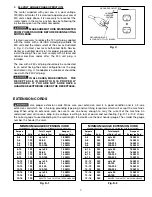
14.
USE THE PROPER EXTENSION CORD.
Make sure
your extension cord is in good condition. When using
an extension cord, be sure to use one heavy enough to
carry the current your product will draw. An undersized
cord will cause a drop in line voltage, resulting in loss of
power and overheating. See the Extension Cord Chart
for the correct size depending on the cord length and
nameplate ampere rating. If in doubt, use the next
heavier gauge. The smaller the gauge number, the
heavier the cord.
15.
SECURE THE WORKPIECE.
Use clamps or a vise to hold
the workpiece when practical. Loss of control of a
workpiece can cause injury.
16.
FEED THE WORKPIECE AGAINST THE DIRECTION OF
THE ROTATION OF THE BLADE, CUTTER, OR ABRASIVE
SURFACE.
Feeding it from the other direction will cause
the workpiece to be thrown out at high speed.
17.
DON’T FORCE THE WORKPIECE ON THE MACHINE.
Damage to the machine and/or injury may result.
18.
DON’T OVERREACH.
Loss of balance can make you
fall into a working machine, causing injury.
19.
NEVER STAND ON THE MACHINE.
Injury could occur if the
tool tips, or if you accidentally contact the cutting tool.
20.
NEVER LEAVE THE MACHINE RUNNING UNATTENDED.
TURN THE POWER OFF.
Don’t leave the machine until it
comes to a complete stop. A child or visitor could be injured.
21.
TURN THE MACHINE “OFF”, AND DISCONNECT THE
MACHINE FROM THE POWER SOURCE
before installing
or removing accessories, before adjusting or changing
set-ups, or when making repairs. An accidental start-up
can cause injury.
22.
MAKE YOUR WORKSHOP CHILDPROOF WITH
PADLOCKS, MASTER SWITCHES, OR BY
REMOVING STARTER KEYS.
The accidental start-up
of a machine by a child or visitor could cause injury.
23
. STAY ALERT, WATCH WHAT YOU ARE DOING, AND
USE COMMON SENSE. DO NOT USE THE
MACHINE WHEN YOU ARE TIRED OR UNDER THE
INFLUENCE OF DRUGS, ALCOHOL, OR MEDICAT-
ION.
A moment of inattention while operating power
tools may result in injury.
24.
TAKE PRECAUTIONS AGAINST DUST INHALATION.
The dust generated by certain woods and wood
products can be injurious to your health. Always
operate machinery in well-ventilated areas, and provide
for proper dust removal. Use wood dust collection
systems whenever possible.
GENERAL SAFETY RULES
READ AND UNDERSTAND ALL WARNINGS AND OPERATING INSTRUCTIONS BEFORE
USING THIS EQUIPMENT. Failure to follow all instructions listed below, may result in electric shock,
fire, and/or serious personal injury or property damage.
IMPORTANT SAFETY INSTRUCTIONS