background image

13

ADJUSTING THE BEVEL MOVEMENT

The bevel-locking force has been set at the factory. After 
a period of time, you may need to adjust the locking 
mechanism. To adjust:

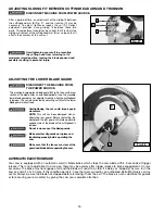
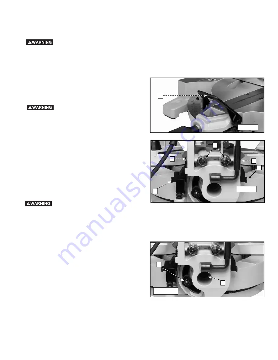
1.  Unlock the bevel locking handle (A) Fig. 22.
2.   Tighten the pivot head nut (C) Fig. 25 such that the 

force to bevel the cutting head by pushing on the 
switch handle is 6-10 pounds.

To check the locking action of the bevel lock handle:
1.  Lock the bevel locking handle (A) Fig. 22.
2.  Check the force to bevel the cutting head by pushing 

on the handle with the cutting head in the full upright 
position. With the bevel locking handle (A) Fig. 22 
down, this force should be 33-35 pounds.

3.  If the bevel action needs adjusting, unlock the bevel 

handle (A) Fig. 22 and loosen or tighten the nut (A) 
Fig. 25 depending on whether you want the bevel 
action tighter or looser.

4.  Close the bevel handle and check the force it takes to 

move the head, as explained in Step 2.

5. Repeat 

if 

necessary.

ADJUSTING 0°, 33.9°, AND 45° BEVEL POSITIVE STOPS

The bevel adjustment utilizes a sliding plate (A) Fig. 20, pin (B), and bushing (C) design feature that can be adjusted to fine-
adjust the bevel angle. The position of the pin within the bushing is adjustable and, when set, determines the bevel angle. To 
adjust, loosen the pin locking screws, move to desired location, and tighten securely.


DISCONNECT MACHINE FROM POWER SOURCE.

1.  Position the bevel detent plate so that the desired angle (A) Fig. 23 is exposed.
2.  Lift the bevel lock lever (A) Fig. 22 to disengage the bevel lock.
3.  Tilt the cuttinghead left until it stops on the plate (A) Fig. 23.
4.  To adjust, loosen the pin locking set screws (D) Fig. 23 (shown from the rear, the screw is located on the side of the 

trunnion between two metal ribs) and rotate the bushing (C) until the red pointer (B) Fig. 19 is at the proper angle. Rotate 
the bushing clockwise to decrease and counterclockwise to increase the bevel angle. Tighten screws (D) securely.

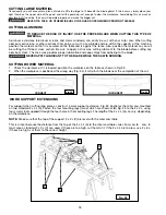
Make sure that the fence is clear of the 
guard and blade before operating the 
saw.

Fig. 22

A

DISCONNECT MACHINE FROM POWER 
SOURCE.

D

A

C

D

A

Fig. 23

NOTE: 

The right bushing adjustment is opposite the 

left.

A

C

Fig. 25

Содержание 36-422L

Страница 1: ...Sierra ingletadora con l ser de doble bisel de 305 mm 12 pulg www deltamachinery com 800 223 7278 US 800 463 3582 CANADA 10 Contractors Saw Model 36 978 36 979 Instruction Manual Manuel d Utilisation...

Страница 2: ...ervice Manager Delta Machinery 4825 Highway 45 North Jackson TN 38305 IN CANADA 125 Mural St Suite 300 Richmond Hill ON L4B 1M4 Information regarding the safe and proper operation of this tool is avai...

Страница 3: ...EMS The symbols below are used to help you recognize this information SAFETY GUIDELINES DEFINITIONS SOME DUST CREATED BY POWER SANDING SAWING GRINDING DRILLING AND OTHER CONSTRUCTION ACTIVITIES contai...

Страница 4: ...damage to the machine or injury to the user 14 USE THE PROPER EXTENSION CORD Make sure your extension cord is in good condition When using an extension cord be sure to use one heavy enough to carry th...

Страница 5: ...e serious injury 19 TIGHTEN THE TABLE CLAMP HANDLE and any other clamps prior to operation Loose clamps can cause parts or the workpiece to be thrown at high speeds 20 NEVER START THE TOOL with the bl...

Страница 6: ...D EXPOSURE LASER LIGHT IS EMITTED FROM FRONT GUARD APERTURE DO NOT DISASSEMBLE LASER MODULE The laser is a CLASS IIIa LASER PRODUCT that can emit laser power up to 5mW MAX at 650 nm which could result...

Страница 7: ...ing this tool The insulation system is for added protection against injury resulting from possible electrical insulation failure within the tool WHEN SERVICING USE ONLY IDENTICAL REPLACEMENT PARTS REP...

Страница 8: ...x 10 dimensional lumber left and right at 45 It has positive miter stops at 0 15 22 5 31 62 and 45 both left and right and bevel stops at 0 33 9 and 45 left Carefully unpack the machine and all loose...

Страница 9: ...new slotted plate design feature D Fig 6 with location adjustment screws E for fine adjusting the cutting angle 2 For proper operation and adjustment of the table refer to sections ROTATING TABLE FOR...

Страница 10: ...surface using C clamps C A Fig 7 FASTENING THE MACHINE TO A SUPPORTING SURFACE FENCE OPERATION A OPERATION OPERATIONAL CONTROLS AND ADJUSTMENTS Fig 8 B A STARTING AND STOPPING THE MACHINE To start th...

Страница 11: ...ver B while turning the table to the desired position After moving the saw place knob A in the locked position by twisting it clockwise until it stops 2 This machine is equipped with positive stops at...

Страница 12: ...on of the pointer B on the scale C 3 In addition a marked indicator D is provided on the bevel scale 33 9 for cutting crown moulding Refer to the CUTTING CROWN MOULDING section of this manual A Fig 18...

Страница 13: ...EVEL POSITIVE STOPS The bevel adjustment utilizes a sliding plate A Fig 20 pin B and bushing C design feature that can be adjusted to fine adjust the bevel angle The position of the pin within the bus...

Страница 14: ...ard along both sides and parallel to the saw blade This beam of light produces a line of cut indicator a red outline of where the saw blade will cut on the workpiece The laser units are aligned to the...

Страница 15: ...ep1 andcontinueto TO SET LEFT AND RIGHT KERF ADJUSTMENT TO SET LEFT and RIGHT KERF ADJUSTMENT 1 Use the 1 8 hex wrench to turn the left or right kerf adjustment screws and set the laser lines to eithe...

Страница 16: ...re of the blade as the cuttinghead is lowered Do not remove any of the blade guards Make sure that all guards are in place and functioning properly before operating the saw Make sure that the fences a...

Страница 17: ...3 mm MACHINE USE A Fig 29A AUXILIARY FENCE SPACER This machine is supplied with new design features that increase cutting capacity The unit can crosscut 4 x 6 dimensional lumber at 0 miter and 0 bevel...

Страница 18: ...ENSIONS For support when cutting long pieces construct a work support extension Fig 35 illustrates the miter saw mounted on two standard 2 x 4 s A Fasten the four mounting legs two of which are shown...

Страница 19: ...Make sure the flats of the molding D Fig M4 are even with the fence and the table as shown Make the cut NOTE The piece of crown moulding used for the inside corner will always be on the right side of...

Страница 20: ...find this angle quickly The saw blade is already tilted to the 33 9 left bevel position from the previous cut 5 Place the crown moulding on the table with the WALL EDGE of the crown moulding against t...

Страница 21: ...C A B D CEILING EDGE WALL EDGE TROUBLESHOOTING For assistance with your machine visit our website at www deltamachinery com for a list of service centers or call the DELTA Machinery help line at 1 800...

Страница 22: ...the spindle NOTE For blades with a blade hole of 5 8 15 88mm the 1 25 4mm blade adapter is not used To install the blade 1 Unplug the saw 2 With the arm raised and the lower guard held open place the...

Страница 23: ...shes are found serviceable after removing reinstall them in the same position DISCONNECT MACHINE FROM POWER SOURCE KEEP MACHINE CLEAN Periodically blow out all air passages with dry compressed air All...

Страница 24: ...line of accessories is available from your Delta Supplier Porter Cable Delta Factory Service Centers and Delta Authorized Service Stations Please visit our Web Site www deltamachinery com for a catal...

Страница 25: ...QUICKSET II QUICKSET PLUS riptide design SAFE GUARD II SAFE LOC Sanding Center SANDTRAP design SAW BOSS Sawbuck Sidekick SPEED BLOC SPEEDMATIC SPEEDTRONIC STAIR EASE The American Woodshop design The...

Отзывы: