Delta 28-278 Скачать руководство пользователя страница 5

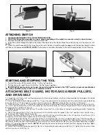
ATTACHING MOTOR TO STAND

Attach the motor to the stand using four 5/16" x 3/4" carriage bolts (A) Fig. 4 (two of which are shown inserted) through
the motor plate (B) and stand (C). Secure the motor to the stand (Fig. 4) from underneath, using external tooth washers (which
should be placed against the underside of the shelf), flat washers and 5/16" hex nuts (F). 

NOTE: 

Partially tighten the motor to

the stand until after belt tension has been adjusted and the pulley has been aligned. Place grommet (D) in large hole in top shelf
(Fig. 4). Insert switch cord and power cord (E) through the hole. 

5

CARTON CONTENTS

ASSEMBLY

ASSEMBLING STAND

Begin the assembly of the stand (Fig. 1) by inserting sixteen 5/16-18 x 5/8" carriage bolts (A) (eight of which are shown)
through the holes in the legs (B) and the holes in the short and long tie bars (C). Secure this part of the assembly by attaching
5/16" hex nuts from the inside. Place the shelf (D) on the inside of the legs, and insert eight 5/16x18 carriage bolts (E) through
the legs (B) and shelf (D). Secure the shelf with flat washers, lock washers and 5/16" hex nuts from the inside. Partially tighten
the hardware at this point.

The top view of the shelf (Fig. 2) illustrates the 4 holes (F) that are used to mount the saw to the stand, and the 4 holes (G) that
are used to mount the motor to the stand. The power cord and the motor-to-switch cord pass through the large hole (H) so that
they are down and out of the way.

Fig. 1

Fig. 2

ATTACHING BAND SAW TO STAND

Attach the band saw (A) Fig. 3 to the stand (B) Fig. 3, using the four 5/16-18 x 1-3/4" hex head screws (two of which are shown
at (C), flat washers, lockwashers and 5/16"-18 hex nuts. Place the hex head screws and lockwashers through the tool base and
the stand. Secure with lock washers and hex nuts from underneath. Push down on top of the stand so that the legs of the stand
adjust to the surface of the floor. Tighten all of the hardware.

Fig. 4

A

A

B

C

B

D

E

E

F

G

G

H

The Delta Model 28-278 comes packaged with the saw, stand, motor, belt and belt guard, pulleys, and hardware.

Fig. 3

A

B

C

D

E

A

B

C

Содержание 28-278

Страница 1: ...NUAL PART NO 426 02 651 0039 08 31 01 Copyright 2001 Delta Machinery To learn more about DELTA MACHINERY visit our website at www deltamachinery com For Parts Service Warranty or other Assistance plea...

Страница 2: ...y to get caught in moving parts Nonslip footwear is recommended Wear pro tective hair covering to contain long hair 12 SECURE WORK Use clamps or a vise to hold work when practical It s safer than usin...

Страница 3: ...rent Before connecting the tool to the power source make sure the switch is in the OFF position GROUNDING INSTRUCTIONS WARNING THIS TOOL MUST BE GROUNDED WHILE IN USE TO PROTECT THE OPERATOR FROM ELEC...

Страница 4: ...0 6 120 25 50 16 AWG 0 6 120 50 100 16 AWG 0 6 120 100 150 14 AWG 6 10 120 up to 25 18 AWG 6 10 120 25 50 16 AWG 6 10 120 50 100 14 AWG 6 10 120 100 150 12 AWG 10 12 120 up to 25 16 AWG 10 12 120 25...

Страница 5: ...f the legs and insert eight 5 16x18 carriage bolts E through the legs B and shelf D Secure the shelf with flat washers lock washers and 5 16 hex nuts from the inside Partially tighten the hardware at...

Страница 6: ...ley L and the motor pulley O are aligned Either pulley can be moved to create proper alignment by loosening the set screw To adjust belt tension loosen the four mounting bolts T two of which are shown...

Страница 7: ...7 7 Fig 9 Fig 14 Fig 11 Fig 10 Fig 12 Fig 13 Fig 16 Fig 15 A B A C D B F H G E C J K B D C L M N L S O V W B T R O B P...

Страница 8: ...t at 90 degrees to the blade Tilt the table to the left until the table stop A Fig 19 contacts the bottom of the table Place a square A Fig 20 on the table and against the blade B Fig 20 and see if th...

Страница 9: ...front edge loosen the wing nut C Fig 23 and tighten the thumb screw D This will draw the blade toward the center of the tire If the blade creeps toward the back edge turn the thumb screw in the oppos...

Страница 10: ...justments and put all guards in place Turn the upper wheel clockwise by hand to be sure that everything is correct prior to connecting tool to power source Keep the top guide close to the work Do not...

Страница 11: ...ICE OR WARRANTY ASSISTANCE All Delta Machines and accessories are manufactured to high quality standards and are serviced by a network of Porter Cable Delta Factory Service Centers and Delta Authorize...

Страница 12: ...tario 91761 Los Angeles 3949A East Guasti Road Phone 909 390 5555 Fax 909 390 5554 San Leandro 94577 Oakland 3039 Teagarden Street Phone 510 357 9762 Fax 510 357 7939 FLORIDA Davie 33314 Miami 4343 So...

Отзывы: