background image


1 0

1.  Connecting to utility power   

Connect the IEC plug of power cord to the IEC 320 connector on the 
UPS. 

Plug the other end of the power cord into a two-pole, three-wire, 
grounding receptacle only. Avoid using extension cords and adapter plug. 

Turn on the input breaker (if the breaker can be turned on) on the rear 
panel of UPS. 

After that, the fan (in rear panel) will run and all LEDs will light for about 
2-3 sec. Meanwhile the CPU inside the UPS setups the initial parameters. 
User also can check whether all LEDs are normal or not. The UPS is set 
in “STANDBY mode” initially, after a ‘bee’ is heard, the load LED lights on 
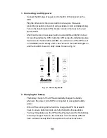
and the line LED shows AC utility status. Shown as fig 3-1. 


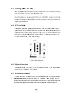
Fig 3-1 Stand-By Mode 


2.  Charging the battery 

The battery charger of the UPS automatically charges the battery 
whenever the power cord of UPS is connected to a acceptable utility 
power.  

When UPS is running for the first time, charge the UPS for at least 6 
hours to ensure batteries inside are fully charged before operation. 

You may immediately use the UPS without having to wait for the batteries 
to be fully charged. However, it is advisable not to do this as UPS will 
have a shorter back-up time than expected if such action is taken. 


Содержание 1KVA

Страница 1: ...R SERIES ON LINE...

Страница 2: ...efore Installation 9 3 3 Installation 9 Chapter 4 OPERATION 14 4 1 Cold start when utility is not present 14 4 2 Turning ON the UPS 14 4 3 Turning OFF the UPS 15 4 4 UPS self test 15 4 5 Silence funct...

Страница 3: ...270 Ritar Falls Sie die Batterien austauschen verwenden Sie bitte ausschlie lich die gleiche Anzahl und die folgenden Batterietypen GES302R 3KVA HR9 12 BB HR1234WF2 34W GES202R 2KVA GP1270 or GP1272F2...

Страница 4: ...guide line of the Council for approximation of the legal regulations of the EC countries concerning the electrical apparatus within certain voltage tolerances modified by the guide line RL 93 68 EEC o...

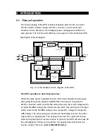
Страница 5: ...ty AC power into a DC voltage which is called DC BUS voltage then divide into two path One path goes to charger which converts the DC BUS voltage into a proper DC voltage to charge the UPS battery The...

Страница 6: ...ures the unit keeps your applications safe and running smoothly at all times PFC Power Factor Correction With this function the investment in the capacity of circuit breakers can be reduced specially...

Страница 7: ...on UPS fault line condition overload etc are simple and easy for user to understand Moreover users can simply reset the circuit breaker instead of having to replace a fuse in the event of output overl...

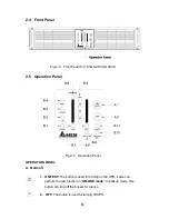
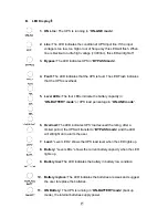
Страница 8: ...Panel Fig 2 5 Operation Panel OPERATION PANEL A Button 1 ON TEST The button is used for turning on the UPS it also can perform the test function in ON LINE mode In backup mode this button can turn of...

Страница 9: ...ttery capacity in ON BATTERY mode or UPS load percentage in ON LINE mode 6 Overload The LED indicates UPS load exceed the rating after a limited period the UPS will transfer to BYPASS mode and the LED...

Страница 10: ...eceptacles 4 SNMP SLOT SNMP adapter can be inserted into this port for monitoring UPS status via network 5 External Batteries Connector Used for connecting external battery cabinets to extend back up...

Страница 11: ...avy objects on the cable or power cord 3 3 Installation Notice AC output need a disconnect device such as a breaker which has to be provided by others The wire length of output power cord connected to...

Страница 12: ...ll LEDs are normal or not The UPS is set in STANDBY mode initially after a bee is heard the load LED lights on and the line LED shows AC utility status Shown as fig 3 1 Fig 3 1 Stand By Mode 2 Chargin...

Страница 13: ...urer suggests that ONE UPS CONNECTS AS MANY AS FIFTEEN EXTERNAL BATTERY BANKS The battery banks should be installed by service personnel According to UL 1778 safety requirement in order to remove the...

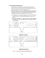
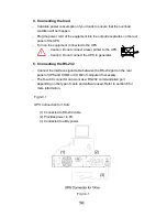
Страница 14: ...printer to the UPS Caution Do not connect the UPS to generator 5 Connecting the RS 232 Connect the interface signal cable between the RS 232 port on the rear panel of UPS and COM1 or COM2 of computer...

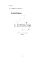
Страница 15: ...1 3 Fig 3 3 2 UPS Connection for 2KVA or 3KVA 1 Connected to RS 232 cable 2 Provides power to PC 3 Connected to utility power Fig 3 3 2...

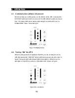
Страница 16: ...battery LED will light on and the UPS runs on ON BATTERY mode Shown as fig 4 1 Fig 4 1 On Battery Mode 4 2 Turning ON the UPS When the utility power is acceptable for the UPS you can normally turn on...

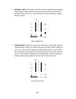
Страница 17: ...rform a self test for about 10 seconds Shown as fig 4 3 The self test function will check the condition of the battery After self test is finished and test is O K the UPS will return to ON LINE mode F...

Страница 18: ...dition Shown as fig 4 5 Fig 4 5 Overload and UPS turn into Bypass BATTERY REPLACE This LED function is to alert user that the batteries should be replaced When the microprocessor in the UPS detects a...

Страница 19: ...tery Low SHORT CIRCUIT When the output of the UPS shorts in ON LINE mode or ON BATTERY mode the UPS will shut down without output voltage As soon as the short circuit is happened the fault LED will li...

Страница 20: ...onent overheats the UPS will protect itself by thermo switches This status is so called O T P When under or over voltage is happened in the UPS output This kind of fault will be detected by the microp...

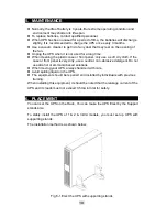
Страница 21: ...t dry cloth If the case or front panel is very dirty use a neutral non abrasive detergent Do not use alcohol or ammonia based solutions When moving your UPS always handle it with care Avoid spilling l...

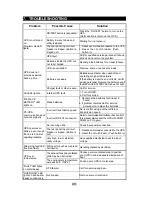
Страница 22: ...batteries 1 Recharge the batteries for at least 8 hours 2 If problem remains Call for service personnel to replace the batteries Incorrect transmission speed Re test after using another different tran...

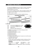
Страница 23: ...ug and play function The RS 232 communication port provides the following functions 1 Monitoring charger status 2 Monitoring battery status and condition 3 Monitoring inverter status 4 Monitoring UPS...

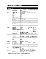
Страница 24: ...7Ah 12V 9Ah Back up Time Typical 5mins 700W 5mins 1400W 5mins 2100W Battery Recharge Time 8 Hours After Complete Discharge to Recover 80 8 Hours After Complete Discharge to Recover 90 Transfer Time T...

Страница 25: ......
Отзывы: