12
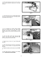
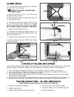
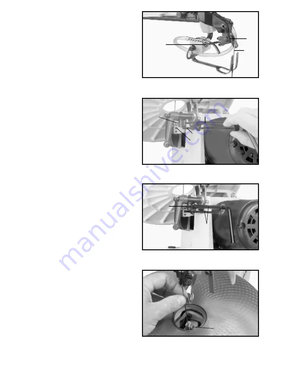
3. Push chuck locking lever (C) Fig. 23, to the rear as
shown. This will release the blade (D) from the upper
chuck (E).
Fig. 23
C
D
E
4.
Insert long end (F) Fig. 24, of quickset blade wrench
into hole (G) in lower blade holder. This will align wrench
(H) with blade holder screw (J).
Fig. 24
G
F
J
H
5.
Fig. 25 illustrates the quickset blade changing
wrench (K) engaged with the lower blade holder
assembly. Turn wrench counterclockwise to loosen
screw (J) Figs. 24 and 25, and remove blade from lower
chuck.
6.
Insert new blade into the lower and upper blade
holders in the same manner, making certain the blade
teeth are pointing down toward the table.
7.
Tighten screw (J) Fig. 26, in lower blade guard
assembly.
8.
Push chuck locking lever (C) Fig. 23, to the foreword
position, to lock the blade in the upper blade holder
assembly.
10. Apply blade tension by referring to the following
section "ADJUSTING BLADE TENSION."
Fig. 25
Fig. 26
K
J
J
9.
Replace the table insert that was removed in STEP
2.
Содержание 16 SM600
Страница 18: ...18 NOTES ...
Страница 19: ...19 NOTES ...
Страница 38: ...38 NOTAS ...
Страница 40: ......
Страница 60: ...60 ...


