Delta 11-900 Скачать руководство пользователя страница 7

7

Use proper extension cords. Make sure your extension
cord is in good condition. When using an extension
cord, be sure to use one heavy enough to carry the
current to your tool. An undersized cord will cause a
drop in line voltage resulting in loss of power and
overheating. Fig. 15 shows the size cord to use
depending on cord length.

If in doubt, use the next heavier gauge. The smaller the
gauge number, the larger the cord size. Use only 3 wire
extension cords which have 3-prong grounding type
plugs and 3-pole receptacles which will accept the tools
plug.

Fig. 15

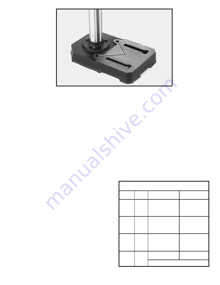
FASTENING DRILL PRESS TO

SUPPORTING SURFACE

If during operation there is any tendency for the drill press to tip over, slide or walk on the supporting surface, the drill
press base must be secured to the supporting surface with fasteners through the two holes (A) Fig. 14, located in the
drill press base.

CONNECTING DRILL PRESS TO POWER SOURCE

POWER CONNECTIONS

A separate electrical circuit should be used for your tools. This circuit should not be less than #12 wire and should be
protected with a 20 Amp fuse. Have a certified electrician replace or repair a damaged or worn cord immediately.
Before connecting the motor to the power line, make sure the switch is in the “OFF” position and be sure that the
electric current is of the same characteristics as stamped on motor nameplate. Running on low voltage will damage
the motor.

Fig. 14

EXTENSION CORDS

A

MINIMUM GAUGE EXTENSION CORD

RECOMMENDED SIZES FOR USE WITH STATIONARY ELECTRIC TOOLS

Ampere       Volts       Total Length of             Gauge of

Rating                         Cord in Feet           Extension Cord

0-6            120             up to 25           

18 AWG

0-6

120             25-50                       16 AWG

0-6            120             50-100                     16 AWG
0-6            120             100-150                   14 AWG
6-10          120             up to 25                   18 AWG
6-10          120             25-50                       16 AWG
6-10          120             50-100                     14 AWG
6-10          120             100-150                   12 AWG      
10-12        120             up to 25                   16 AWG
10-12        120             25-50                       16 AWG
10-12        120             50-100                     14 AWG
10-12        120             100-150                   12 AWG
12-16        120             up to 25                   14 AWG
12-16        120             25-50                       12 AWG       
12-16        120          

GREATER THAN 50 FEET NOT RECOMMENDED

Содержание 11-900

Страница 1: ...RT NO 900585 011 Copyright 2001 Delta Machinery ESPAÑOL PÁGINA 17 To learn more about DELTA MACHINERY visit our website at www deltamachinery com For Parts Service Warranty or other Assistance please call 1 800 223 7278 In Canada call 1 800 463 3582 ...

Страница 2: ...yeglasses only have impact resistant lenses they are not safety glasses Also use face or dust mask if cutting operation is dusty These safety glasses must conform to ANSI Z87 1 requirements Note Approved glasses have Z87 printed or stamped on them 13 SECURE WORK Use clamps or a vise to hold work when practical It s safer than using your hand and frees both hands to operate tool 14 DON T OVERREACH ...

Страница 3: ... SAVE THESE INSTRUCTIONS ADDITIONAL SAFETY RULES FOR DRILL PRESSES 14 BE SURE drill bit or cutting tool is not damaged and is properly locked in the chuck before operating 15 MAKE SURE chuck key is removed from chuck before starting drill press ONLY use chuck key provided with your drill press It is equipped with a self ejecting pin which eliminates the hazard of the key being left in the chuck 16...

Страница 4: ...d with the machine WARNING FOR YOUR OWN SAFETY DO NOT CONNECT THE DRILL PRESS TO THE POWER SOURCE UNTIL THE MACHINE IS COMPLETELY ASSEMBLED AND YOU HAVE READ AND UNDERSTOOD THE ENTIRE INSTRUCTION MANUAL Fig 2 1 Drill Press Head and Motor 2 Column and Base Flange 3 Base 4 Table 5 Chuck 6 Chuck key 7 Clamp handle 8 Wrench 9 M8 x 20mm Hex head screw 3 10 Pinion Shaft Handles 3 Fig 3 1 2 3 4 10 9 8 7 ...

Страница 5: ...oline or lacquer thinner for this purpose ASSEMBLING THE DRILL PRESS Fig 4 Fig 5 Fig 6 1 Assemble the column A Fig 4 to drill press base B as shown using the three M8 x 20mm hex head cap screws C 2 Assemble the table D Fig 5 to drill press column A as shown 3 Thread clamp handle E Fig 6 into holes in rear of table bracket as shown Align table D to base B and tighten clamp handle E A C B C A D D B ...

Страница 6: ...es must be clean to ensure that the chuck will adhere to the spindle and will not come loose during operation NOTE Household oven cleaner can effectively remove the rust protectant coating from the spindle and chuck however carefully follow the manufacturer s safety rules concerning its use Then push the chuck M up on the spindle K as far as it will go 7 IMPORTANT Open the chuck jaws as wide as po...

Страница 7: ...RILL PRESS TO POWER SOURCE POWER CONNECTIONS A separate electrical circuit should be used for your tools This circuit should not be less than 12 wire and should be protected with a 20 Amp fuse Have a certified electrician replace or repair a damaged or worn cord immediately Before connecting the motor to the power line make sure the switch is in the OFF position and be sure that the electric curre...

Страница 8: ...t grounding conductor If repair or replacement of the electric cord or plug is necessary do not connect the equipment grounding conductor to a live terminal Check with a qualified electrician or service personnel if the grounding instructions are not completely understood or if in doubt as to whether the tool is properly grounded Use only 3 wire extension cords that have 3 prong grounding types pl...

Страница 9: ...ll it out of the switch as shown in Fig 19 With the switch toggle B removed the switch will not operate However should the switch toggle be removed while the drill press is operating the switch can be turned OFF once but cannot be restarted without inserting the switch toggle B TABLE ADJUSTMENTS 1 The table can be raised or lowered on the drill press column by loosening the table clamp handle A Fi...

Страница 10: ...0 and 3100 RPM are available with your drill press The highest speed is obtained when the belt is on the largest step of the motor pulley and the smallest step of the spindle pulley as shown in Fig 25 Fig 25 illustrates which step of the motor and spindle pulley the belt must be placed to obtain the five speeds available SPINDLE MOTOR 3100 2340 1720 1100 620 Fig 22 4 A tilt scale E Fig 23 is provi...

Страница 11: ... toward the front of the drill press head position the belt C on the desired steps of the motor and spindle pulleys as shown in Fig 27 5 After the belt is positioned on the desired steps of the motor and spindle pulleys pivot motor D Fig 27 away from the drill press head until the belt is properly tensioned and tighten tension lock knob B The belt should be just tight enough to prevent slipping Ex...

Страница 12: ...ETURN SPRING The spindle is automatically returned to its upper most position upon release of the handle It is recommended that the handle be allowed to slowly return to the top position after all holes have been bored in the material This spring has been properly adjusted at the factory and should not be disturbed unless absolutely necessary To adjust the return spring proceed as follows WARNING ...

Страница 13: ...he hazard of the key being left in the chuck Fig 30 CORRECT DRILLING SPEEDS Factors which determine the best speed to use in any drill press operations are material size of hole type of drill or other cutter and quality of cut desired The smaller the drill the greater the RPM required When drilling in soft materials use a higher speed than what would be used for harder materials OPERATION Your dri...

Страница 14: ...e or personal injury to the operator If it is not possible to support the workpiece against the column the workpiece should always be fastened to the table using clamps or a vise Feed slowly when the bit is about to cut through the wood to prevent splintering the bottom face Use a scrap piece of wood A Fig 33 for a base block under the work this helps to reduce splintering and protects the point o...

Страница 15: ...15 NOTES ...

Страница 16: ...from normal wear misuse abuse or repair or alteration made or specifically authorized by anyone other than an authorized Delta Service facility or representative Under no circumstances will Delta be liable for incidental or consequential damages resulting from defective products This warranty is Delta s sole warranty and sets forth the customer s exclusive remedy with respect to defective products...

Отзывы: