TROUBLE SHOOTING
SM3300
26 / 30
DELTA ELEKTRONIKA B.V.
rev. Jan. 2022
8
TROUBLE SHOOTING
8.1
GENERAL
If you have a question about the unit, please contact our
engineers using the address [email protected].
In case the unit is defect, please first fill out the RMA-form
before sending the unit to us. Adding a detailed fault
description will help us to repair the unit as soon as
possible. Do not try to repair the unit yourself.
On our website the RMA-form can be found under
'Support'.
8.2
NO DC OUTPUT
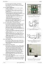
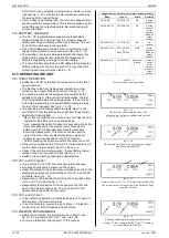
Check the output is switched ON: the text 'ON/off' must be
visible on the right side of the display.
If the text is 'on/OFF', press the button next to this text to
switch it ON if needed.
Check the unit is not in LOCK mode: the text 'Lock' must be
visible on the right side of the display.
If the text is 'Unlock', press the button next to this text for a
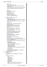
few seconds to unlock the unit, see fig. 8 - 1.
First set the unit in local operation (or so-called manual
operation): press and hold the ON/off button for 4 seconds.
On the second line of the display, before both the set
values the text 'front' will be seen, now press the button
next to the text on/OFF to switch on the output.
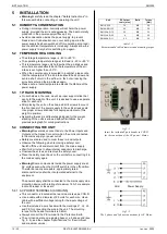
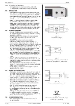
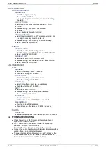
Check the connections on the SENSE BLOCK (at rear
panel). For local sensing, there should be a link b
and S+ and between
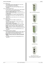
– and S– (see fig. 8 - 2).
For remote sensing, the wires from S+ and S- should be
connected to respectively the + and - terminals on the load.
Check there is a link between pin 1 and pin 3 of the
Interlock connector.
Check the settings for CV- and CC-limit are set to a value
greater than 0.
Go to Menu -> Protection -> Limits.
Here set Voltage and Current limits.
Turn both the CV and CC encoders a few turns clockwise.
Now a voltage should be present on the output.
8.3
PROGRAMMING DOES NOT WORK OK
First make sure the unit works ok in local mode, see
previous paragraph.
If this is okay, check the unit is in Remote mode.
Go to Menu -> Configuration -> Source.
Here set the Vsettings and Isettings to the required
programming source, either 'eth', 'web', 'slot1', 'slot2', 'slot3'
or 'slot4'.
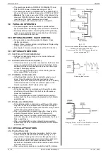
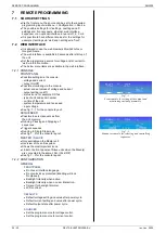
For example, when programming via Ethernet, on the
second line of the display, before both the set values the
text 'eth' must be seen.
It is also possible to only have only one of the settings in
remote mode, and have the other setting in local mode.
Enter a command to program both the CV and CC setting
to a value greater than 0.
Now a voltage should be present on the output.
8.4
MASTER / SLAVE PARALLEL PROBLEMS
Check the voltage drop of the wiring between the master
and the slaves is < 10 mV.
Check the wiring has a low inductance.
See interface manual for more trouble shooting.
8.5
OUTPUT VOLTAGE IS HIGHER THAN SET
VALUE
Check connections on SENSE BLOCK (on rear panel), For
normal operation there should be a link b and S+
and between
– and S– (see also fig. 8 - 2 ).
When remote sensing is used, check the wires of the
sensing.
fig 8 - 2
For normal operation links should be connected
between S+ and +, and between S– and –.
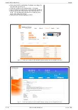
fig 8 - 1
At the right side, the texts must be 'Lock'
and 'ON/off'.
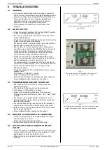
fig 8 - 3
For Ethernet programming, the text 'eth' must be seen
before the setting(s) that is/are in 'remote mode'.

