


GENERAL
SM6000
7 / 21
DELTA ELEKTRONIKA B.V.
rev. Nov. 2020
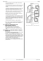
terminals using a probe with very short connections. This to
avoid pick up of magnetic fields, see fig. 3 - 2 and fig. 3 - 3.
At low temperatures like -20°C the ripple increases. By using
high quality electrolytic capacitors the increase is relatively
low.
3.9
ANALOG PROGRAMMING
The DC output voltage and current can be programmed by an
external analog voltage. This programming is very accurate
and linear. The levels are all standardized on 5 V.
Standard the SM300-20 and SM600-10 are equipped with the
ISO-AMP, see next paragraph.
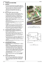
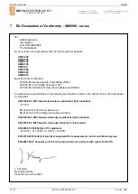
For the other units, the inputs have a protection circuit formed
by a series resistor and a parallel zener (see fig. 3 - 4).
The capacitor limits the speed to a safe value.
Note that the
analog inputs (and outputs) are not floating, but the
common is connected to the 'minus' DC output terminal.
Wrong connection of Ø can cause earth loops which can trip
the fuse. After removing the fault, the fuse will reset (PTC-
fuse). For isolated programming see next paragraph.
3.10
ISOLATED ANALOG PROGRAMMING
To prevent earth loops which can cause programming errors,
use an isolated programming source. If this is not possible,
use the optional
ISO AMP CARD
which can be built inside
the unit.
With the ISO AMP CARD earth loops between the unit and
the programming source are prevented.
3.11
ETH / IEEE488 / RS232 PROGRAMMING
The Delta Elektronika
PSC-ETH, PSC-488 and PSC-232
controllers can be factory installed inside the unit.
Voltage and current can easily be programmed and read
back. Also all the status outputs can be read by the computer.
3.12
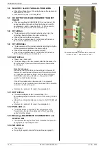
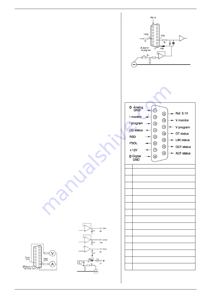
MONITORING OUTPUTS
The monitor outputs give a voltage 0 - 5 V proportional to the
output current or voltage. The output current can easily be
measured using the I-monitor (see fig. 3 - 6). The monitor
outputs are buffered with op-
amp’s and protected with series
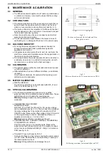
resistors and parallel zener diodes (see fig. 3 - 7). The table in
fig. 3 - 5 shows the impedance levels of the monitoring
outputs. For using Imon on a pulsating load, see paragraph
20) of this chapter.
3.13
+12 V ON PROGRAMMING CONNECTOR
The +12 V on the programming connector can be used to
supply external circuits. The output is current limited, but
should not be overloaded. The fuse F27_3 on P598 could
blow. The fuse F27_3 also protects the internal circuit, in case
an external high voltage is applied by accident. Note: this fuse
is a special 600 V type, always replace with the same type.
fig 3 - 4
Programming inputs (internal circuit).
fig 3 - 6
External meters using monitor
outputs.
pin
Description, see par.12)...17) for details
1
Ø, return of reference, prog. inputs and monitor
outputs (Ro = 1.2 Ohm).
2
current monitor output 0 - 5 V
(Ro = 1.2 Ohm, Io max = 4 mA)
3
current programming input (0 - 5 V),
Ri = 8 MOhm
4
CC status output, logic 1 = CC mode
(5 V / 500 Ohm)
5
Remote ShutDown (4 - 12 V),
Ri = 5 kOhm
6
PSOL status output, logic 1 = PSOL
(5 V / 500 Ohm)
7
+12 V output
(Ro = 3 Ohm, Io max = 0.2 A)
8
Ø, return of status outputs, +12 V
and Remote ShutDown
9
reference voltage 5.1 V
(Ro = 1.2 Ohm, Io max = 4 mA)
10
voltage monitor output 0 - 5 V
Ro = 1.2 Ohm, Io max = 4 mA)
11
voltage programming input (0 - 5 V)
Ri = 8 MOhm
12
OT - status output, logic 1 = OT
(5 V / 500 Ohm)
13
LIM - status output, logic 1 = LIM
(5 V / 500 Ohm)
14
DCF - status output, logic 1 = DCF
(5 V / 500 Ohm)
15
ACF - status output, logic 1 = ACF
(5 V / 500 Ohm)
fig 3 -5
Connections ANALOG PROG. CONNECTOR.
fig 3 - 7
Buffered monitor outputs.