


www.delta-controls.com
IOM-GR-A : AUGUST 2016
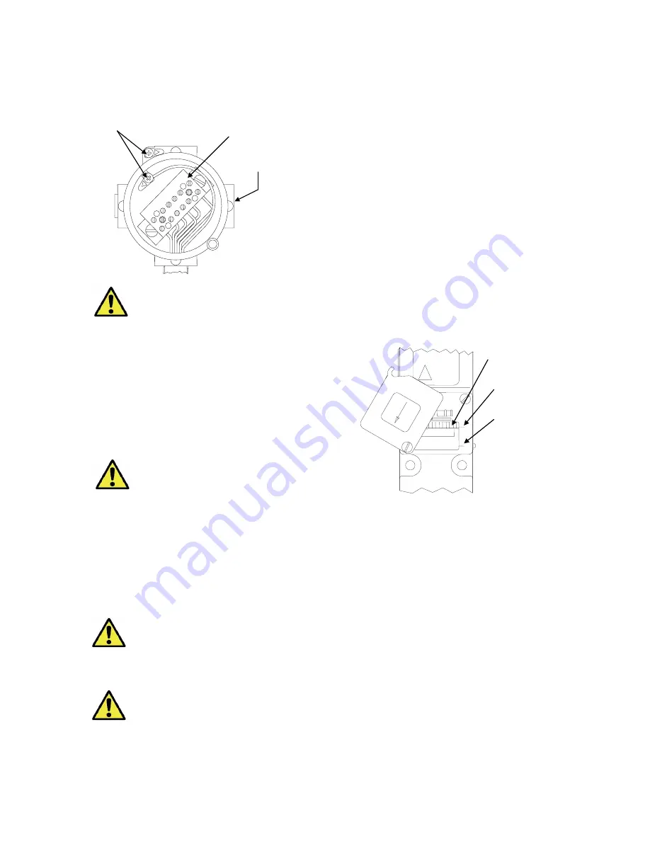
Wiring - when Junction Box is fitted
(See Fig. 4)
Some models may be provided with an integral
weatherproof or Ex junction box.
WIRE IN ACCORDANCE WITH LOCAL
AND NATIONAL CODES. USE CABLES
NO LARGER THAN 2.5 MM² (14 AWG)
Insert bare wires fully into the terminal block and
tighten securely. Keep wiring tails to a minimum.
End of line resistors
Some products may be supplied to order fitted with
end of line resistors. Resistors in use may generate
a heat source. The type, quantity, configuration,
fitment method and allowable electrical loads are
limited by the scope of the certification.
NEVER FIT END OF LINE RESISTORS OR
MODIFY WITHOUT REFERENCE TO
DELTA CONTROLS
Replacing
cover
on
Flameproof
enclosures
Before connecting to electrical power, screw on
cover hand tight making sure that mating surfaces of
the lid and enclosure are in contact. Use the locking
screws provided to prevent casual and unauthorised
removal of the cover.
DO
NOT
USE
GREASES
OR
LUBRICANTS NOT COMPATIBLE WITH
THE
ENVIROMENT,
PROCESS
OR
ALUMINIUM.
IT IS A SAFETY REQUIREMENT THAT AT
LEAST 5 FULL THREADS ARE ENGAGED
BETWEEN THE COVER / LID AND THE
ENCLOSURE WHEN THE UNIT IS IN
OPERATION. NEVER OPERATE THE
UNIT UNLESS THIS CONDITION IS MET.
OPERATION
Adjustments
Pressure and Temperature Switches are supplied
calibrated at the midpoint of their range and to a
falling pressure or temperature unless otherwise
specified.
Set point adjustments (All Models)
:
(See Fig. 5)
1. Isolate the instrument from process and power
(Adjustment may be carried out with the unit live)
2. Loosen both cover screws
3. Rotate cover anti-clockwise to allow access.
4. Using a screwdriver, rotate the range adjuster to
obtain the desire setting. Turn right to left to
increase the setting. An appropriate setting is
shown by pointer against reference scale.
5. Rotate cover clockwise to close and tighten
screws.
As a guide, one complete revolution of the adjuster
will alter the set point by approximately 15% of the
range.
Note:
For accurate setting of Pressure and
Differential Pressure models, a suitable pressure
gauge must be used in conjunction with the above
procedure. Do not attempt to set the switch outside
the scale limits. For Temperature models a suitable
calibrated temperature source should be used.
Though the unit may be set anywhere within its
range, for optimum performance, it is good practice
to have a set point value between 25% and 75% of
span.
Process configurations (Models GR3,
GR6 - other than range BC)
For normal pressure difference operation, the
connections are made to the High Pressure (HP)
and Low Pressure (LP) ports as appropriate. For
single-ended positive pressure operation, the HP
only is used and the LP is left open to atmosphere.
The single-ended negative pressure operation, the
LP only is used and the HP is left open to
atmosphere.
Use a breather / filter in the vacant port of single-
ended operation.
SCREW DRIVER
LOCATION SLOTS
LOWEST SET POINT
HIGHEST SET POINT
ADJUST RIGHT TO
LEFT TO INCREASE
SET POINT
Fig 3
ATEX
ATEX
Fig 5
ATEX
ATEX
NC
COM
NO
NC
COM
NO
EARTH SCREW
TERMINAL BLOCK
NORMAL R H
ELECTRICAL ENTRY
Fig 2
Fig 4


