


Document Edition 2.4
Input Configuration
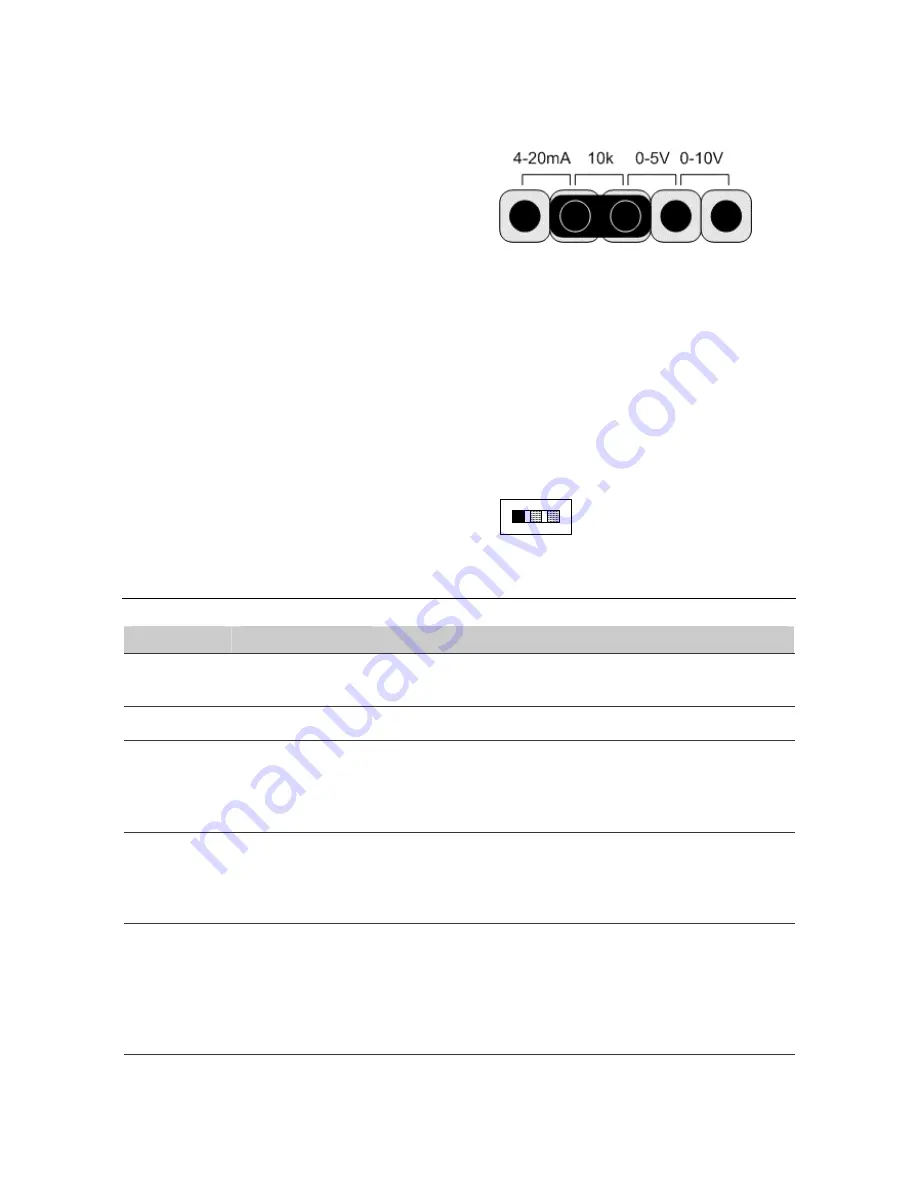
The input must be configured to accept the signal used by
the input device. Place the jumper for each input in the
correct location on the Input Type Selector Block. The
diagram to the right shows the factory default selection of
10 K
Ω
.
4-20mA
For sensors that use a 4 to 20 mA signal.
10K
For 10 K
Ω
Thermistor temperature
sensors, as well as Dry Contact binary
inputs.
5V
For sensors that use a 0 - 5 VDC signal.
10V
For sensors that use a 0 -10 VDC signal.
Output Configuration
Each HOA switch is HAND, OFF, AUTO from right to left.
The HAND position allows a user to manually force the
output on, the OFF position allows a user to manually force
an output off, and the AUTO position allows the output to
be controlled automatically by the controller.
AUT
O
OF
F
HAND
Indicators
LED
Function
Description
Power Controller
Power
Indicator
This yellow LED turns on to indicate that the controller has power
applied.
Scan
CPU Scan Indicator
This red LED flashes at a rate relative to the CPU scan rate.
Network
(NET1)
LINKnet (RS485)
Communication
Status Indicators
The green LED flashes to indicate when the controller is
transmitting out the port, and the red LED flashes to indicate when
the controller is receiving data through the port. If communication
is good, both LEDs will flash at a high rate.
Inputs
(IP1 – IP16)
Input Status
Indicators
A corresponding red LED varies in intensity and is brightly lit when
the associated input is receiving a low voltage input signal (i.e. a
closed contact, 0 VDC, 0mA or a high temperature reading or low
resistance).
Outputs
(OP1 – OP16)
Output Status
Indicators
A tri-color LED is used. Under automatic control, the
corresponding output LED is green and is on or off to match the
status of an associated binary output. The LED will also vary in
intensity relative to the output signal for an analog output. With
HOA switches, the output LED is red in the OFF position and
yellow in the HAND position.
Page 7 of 10


