Access Door Module ADM-2W704 (Rev 1.3) Installation & Application Guide
Page 6 of 26
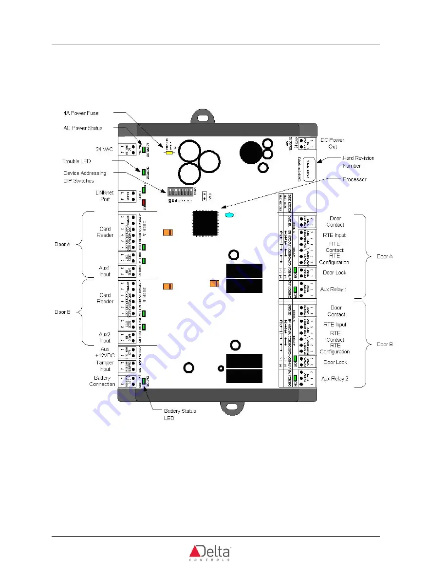
Access Door Module
B
OARD
L
AYOUT
(A
CCESS
D
OOR
M
ODULE
)
All Terminal Class 2
Страница 1: ...etworked together to a maximum of 12 Access Door Modules to provide access control of up to 24 doors TABLE OF CONTENTS PRODUCT DESCRIPTION 1 TABLE OF CONTENTS 1 MODEL NUMBERS 2 UL AUTHORIZED ACCESSORI...
Страница 2: ...ad Range Single Gang Box Mount Sentinel Prox SR 2400 4 to 5 5 inch Read Range Metal Compensated Indoor Outdoor Sentinel Prox MM 6800 6 to 8 inch Read Range Metal Compensated Indoor Outdoor Sentinel Pr...
Страница 3: ...battery charging and battery back up of the controller as well as all devices connected and powered from the controller DC Power out 14 VDC 0 25A with a resetable fuse can supply one Access System Man...
Страница 4: ...tatus o 1 Battery Status o 2 Door 5 VDC Power Status o 2 Door 12 VDC Power Status Outputs 2 Door Locks Form C Relay rated 24VDC AC 5A with MOV protection internally supplied with 12 VDC as above 2 Aux...
Страница 5: ...oys Wiegand 26 communication protocol and was verified in the evaluation UL has not evaluated the following features of the ADM 2W704 and therefore should not to be connected in UL applications Batter...
Страница 6: ...Access Door Module ADM 2W704 Rev 1 3 Installation Application Guide Page 6 of 26 Access Door Module BOARD LAYOUT ACCESS DOOR MODULE All Terminal Class 2...
Страница 7: ...he associated output CONTROLLER ADDRESS DIP SWITCHES Each individual DIP switch represents a pre defined value as printed on PCB beside the address block which added together forms the device address...
Страница 8: ...ield wires into the terminal blocks BATTERY BACKUP WIRING NOT TO BE CONNECTED IN UL APPLICATIONS The Access Door Module has been designed with a battery circuit to provide the option of both battery c...
Страница 9: ...Delta Controls Access Door Module Page 9 of 26 24 VAC Access Door Module Power Connection Wiring Detail Battery Connection Wiring Detail Not evaluated by UL...
Страница 10: ...ss Door Module ADM 2W704 Rev 1 3 Installation Application Guide Page 10 of 26 Access Door Module DC Power Out Used Power and Battery Backup Access System Manager Auxiliary Power Wiring Not Evaluated b...
Страница 11: ...duct is shipped configured as a Fail Secure door See diagram below The tamper switch input is connected to a standard single contact switch such as the Locknetics Security Model 7766 either the N O or...
Страница 12: ...oor Module 12 VDC is a linear power supply which is required by most proximity card reader manufacturers You should follow the wiring and wire type specifications of the card reader manufacturer that...
Страница 13: ...Delta Controls Access Door Module Page 13 of 26 AWID HID Prox Card Reader Wiring...
Страница 14: ...ieve the status and to interrupt the Door Lock for egress The table and diagram below show how the Request to Exit should be configured and wired for the Door Lock type chosen When using a Type 3 or T...
Страница 15: ...t configure the circuit If the Door Lock is configured as fail safe a jumper needs to be put in place of the RTE Contact The diagram below shows how the RTE circuit is configured when not using an RTE...
Страница 16: ...rams below Each EOL circuit is based on 10K Ohm 5 resistors EOL resistors should be installed at the end of the line at the device not at the Access Door Module controller Placing an EOL at the Access...
Страница 17: ...onitor supervise a Normally Open contact to indicate Trouble when there is an Open Circuit wires cut A short circuit contact bypassed will not indicate Trouble but will generate an Alarm condition Con...
Страница 18: ...y Open contacts When using a Type 3 or Type 4 EOL Circuit and a Request to Exit button that has a single pole switch make sure that the 10K Ohm resistor is on the input leg of the circuit not the grou...
Страница 19: ...the Type 3 or Type 4 EOL Circuit and a Request to Exit button that has a single pole switch make sure that the 10K Ohm resistor is on the input leg of the circuit not the ground side of the circuit o...
Страница 20: ...elay Output SPDT Not to be connected in UL applications BO7 B LED1 BO8 B LED2 BO9 N A Trouble LED Door Lock Wiring Detail The Door Lock output is wired straight back to the Access Door Module as shown...
Страница 21: ...h door is an SPDT relay and can be wired as N O and or N C It is controlled from a single software output The contacts are rated at 24VAC DC 5A Wiring Detail for switching a large load 120VAC Motor is...
Страница 22: ...ty of propagation of 66 or higher Topology Ensure the cable is installed as a daisy chain from one device to the next Max Controllers Access Door Modules The maximum number of controllers per LINKnet...
Страница 23: ...OLOGY CONFIGURATION NOT EVALUATED BY UL With V3 22 firmware the Access Door Module is a LINKnet device that acts as extended I O to the master controller the Access System Manager Up to 12 Access Door...
Страница 24: ...al Reference Manual for further details on configuring the LINKnet network or changing baud rates etc See RS 485 Network Installation Guide DOC818 11 for details on wiring and terminating the LINKnet...
Страница 25: ...uations Pst 1 Plt 0 65 EN 61000 6 1 2007 Generic Immunity Standard Part 1 Light Industrial Residential EN 55024 2010 Immunity Requirements for Information Technology Equipment EN 61000 4 2 ESD Immunit...
Страница 26: ...ipment is operated in a commercial environment This equipment generates uses and can radiate radio frequency energy and if not installed and used in accordance with the instruction manual may cause ha...