background image

Removing the base cover

WARNING: 

Before working inside your computer, read the safety information that shipped with your computer and follow the 

steps in 

Before working inside your computer

. After working inside your computer, follow the instructions in 

After working inside 

your computer

. For more safety best practices, see the Regulatory Compliance home page a

www.dell.com/

regulatory_compliance

.

Procedure

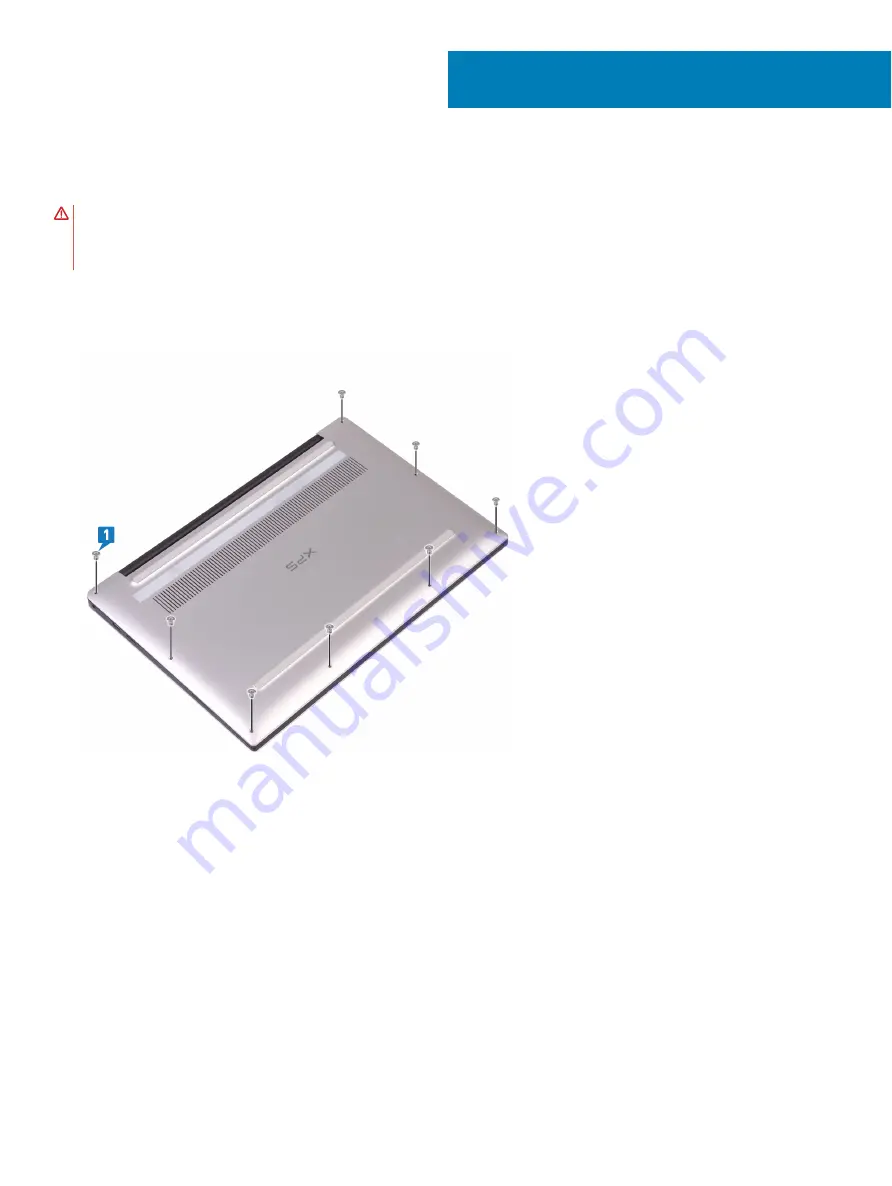
Remove the eight screws (M2x3, Torx) that secure the base cover to the palm-rest assembly.

With the computer face-down, open the computer at an angle.

Using a plastic scribe, pry the base cover from the palm-rest assembly.

6

Removing the base cover

15

Содержание XPS 9380

Страница 1: ...XPS 9380 Service Manual Computer Model XPS 9380 Regulatory Model P82G Regulatory Type P82G002 ...

Страница 2: ...age to hardware or loss of data and tells you how to avoid the problem WARNING A WARNING indicates a potential for property damage personal injury or death 2018 2019 Dell Inc or its subsidiaries All rights reserved Dell EMC and other trademarks are trademarks of Dell Inc or its subsidiaries Other trademarks may be trademarks of their respective owners 2019 02 Rev A01 ...

Страница 3: ...t 11 4 Recommended tools 12 5 Screw list 13 6 Removing the base cover 15 Procedure 15 7 Replacing the base cover 18 Procedure 18 8 Removing the battery 20 Lithium ion battery precautions 20 Prerequisites 20 Procedure 20 9 Replacing the battery 22 Lithium ion battery precautions 22 Procedure 22 Post requisites 23 10 Removing the solid state drive 24 Prerequisites 24 Procedure 24 11 Replacing the so...

Страница 4: ...nk 31 Procedure 31 Post requisites 31 18 Removing the display assembly 32 Prerequisites 32 Procedure 32 19 Replacing the display assembly 34 Procedure 34 Post requisites 35 20 Removing the headset port 36 Prerequisites 36 Procedure 36 21 Replacing the headset port 38 Procedure 38 Post requisites 39 22 Removing the fans 40 Prerequisites 40 Procedure 40 23 Replacing the fans 42 Procedure 42 Post req...

Страница 5: ...Post requisites 51 30 Removing the palm rest assembly 52 Prerequisites 52 Procedure 52 31 Replacing the palm rest assembly 53 Procedure 53 Post requisites 53 32 Device drivers 54 Intel Chipset Software Installation Utility 54 Video drivers 54 Intel Serial IO driver 54 Intel Trusted Execution Engine Interface 54 Intel Virtual Button driver 54 Wireless and Bluetooth drivers 54 33 System setup 55 Sys...

Страница 6: ...d Pre Boot System Assessment ePSA diagnostics 62 Running the ePSA diagnostics 62 System diagnostic lights 62 Flashing BIOS USB key 63 Flashing the BIOS 64 Flea power release 64 Wi Fi power cycle 64 6 Contents ...

Страница 7: ... Start Power Shut down NOTE If you are using a different operating system see the documentation of your operating system for shut down instructions 3 Disconnect your computer and all attached devices from their electrical outlets 4 Disconnect all attached network devices and peripherals such as keyboard mouse and monitor from your computer 5 Remove any media card and optical disc from your compute...

Страница 8: ...y screws remain inside your computer 2 Connect any external devices peripherals or cables you removed before working on your computer 3 Replace any media cards discs or any other parts that you removed before working on your computer 4 Connect your computer and all attached devices to their electrical outlets 5 Turn on your computer 2 8 After working inside your computer ...

Страница 9: ... concern when you handle electronic components especially sensitive components such as expansion cards processors memory DIMMs and system boards Very slight charges can damage circuits in ways that may not be obvious such as intermittent problems or a shortened product life span As the industry pushes for lower power requirements and increased density ESD protection is an increasing concern Due to...

Страница 10: ...egional office to find out if they have one To perform the test plug the wrist strap s bonding wire into the tester while it is strapped to your wrist and push the button to test A green LED is lit if the test is successful a red LED is lit and an alarm sounds if the test fails Insulator Elements It is critical to keep ESD sensitive devices such as plastic heat sink casings away from internal part...

Страница 11: ... mechanical lifting device 1 Get a firm balanced footing Keep your feet apart for a stable base and point your toes out 2 Tighten stomach muscles Abdominal muscles support your spine when you lift offsetting the force of the load 3 Lift with your legs not your back 4 Keep the load close The closer it is to your spine the less force it exerts on your back 5 Keep your back upright whether lifting or...

Страница 12: ...Recommended tools The procedures in this document may require the following tools Philips screwdriver 0 Philips screwdriver 1 Torx 5 T5 screwdriver Plastic scribe 4 12 Recommended tools ...

Страница 13: ...ed Table 1 Screw list Component Secured to Screw type Quantity Screw image Keyboard Palm rest assembly M1 6x1 5 29 Fingerprint reader board NOTE This component is only available on systems with fingerprint reader integrated on the power button Palm rest assembly M1 6x1 5 1 Power button Palm rest assembly M1 4x1 7 2 System board Palm rest assembly M1 6x2 5 10 Fans System board M1 6x3L 2 Speakers Pa...

Страница 14: ...crew type Quantity Screw image Solid state drive shield and solid state drive System board M2x3L 1 Battery Palm rest assembly M2x2 4 Battery Palm rest assembly M1 6x4 1 Base cover Palm rest assembly M2x3 Torx 8 14 Screw list ...

Страница 15: ...low the instructions in After working inside your computer For more safety best practices see the Regulatory Compliance home page at www dell com regulatory_compliance Procedure 1 Remove the eight screws M2x3 Torx that secure the base cover to the palm rest assembly 2 With the computer face down open the computer at an angle 3 Using a plastic scribe pry the base cover from the palm rest assembly 6...

Страница 16: ...over from left to right release the clips securing the base cover to the palm rest assembly 5 Lift the base cover from the palm rest assembly 6 Disconnect the battery cable from the system board 16 Removing the base cover ...

Страница 17: ...Removing the base cover 17 ...

Страница 18: ...nside your computer follow the instructions in After working inside your computer For more safety best practices see the Regulatory Compliance home page at www dell com regulatory_compliance Procedure 1 Connect the battery cable to the system board 2 Align the screw holes on the base cover with the screw holes on the palm rest assembly and slide in the base cover into place 7 18 Replacing the base...

Страница 19: ...3 Replace the eight screws M2x3 Torx that secure the base cover to the palm rest assembly Replacing the base cover 19 ...

Страница 20: ...attery to drain Do not crush drop mutilate or penetrate the battery with foreign objects Do not expose the battery to high temperatures or disassemble battery packs and cells Do not apply pressure to the surface of the battery Do not bend the battery Do not use tools of any kind to pry on or against the battery If a battery gets stuck in a device as a result of swelling do not try to free it as pu...

Страница 21: ...st assembly 3 Remove the screw M1 6x4 that secures the battery to the palm rest assembly 4 Lift the battery off the palm rest assembly 5 Turn the computer over open the display and press the power button for about 5 seconds to ground the computer Removing the battery 21 ...

Страница 22: ...th foreign objects Do not expose the battery to high temperatures or disassemble battery packs and cells Do not apply pressure to the surface of the battery Do not bend the battery Do not use tools of any kind to pry on or against the battery If a battery gets stuck in a device as a result of swelling do not try to free it as puncturing bending or crushing a Lithium ion battery can be dangerous In...

Страница 23: ...Post requisites Replace the base cover Replacing the battery 23 ...

Страница 24: ...pliance CAUTION Solid state drives are fragile Exercise care when handling the solid state drive CAUTION To avoid data loss do not remove the solid state drive while the computer is in sleep or on state Prerequisites Remove the base cover Procedure 1 Remove the screw M2x3 that secures the solid state drive shield and the solid state drive to the system board 2 Slide and remove the solid state driv...

Страница 25: ...N Solid state drives are fragile Exercise care when handling the solid state drive Procedure 1 Align the notches on the solid state drive with the tabs in the solid state drive slot then slide the solid state drive at an angle into the solid state drive slot 2 Slide the solid state drive shield into the solid state drive shield slot Then align the screw hole on the solid state drive shield and sol...

Страница 26: ... see the Regulatory Compliance home page at www dell com regulatory_compliance Prerequisites 1 Remove the base cover 2 Remove the battery Procedure 1 Disconnect the speaker cable from the system board 2 Remove the four screws M2x2 that secure the left and right speakers to the palm rest assembly 3 Note the speaker cable routing and peel off the tapes 4 that secure the speaker cable to the keyboard...

Страница 27: ...www dell com regulatory_compliance Procedure 1 Using the alignment posts on the palm rest assembly place the left speaker on the palm rest assembly 2 Route the speaker cable on the system board and adhere the tape to the system board 3 Using the alignment posts on the palm rest assembly place the right speaker on the palm rest assembly 4 Replace the four screws M2x2 that secure the speakers to the...

Страница 28: ...best practices see the Regulatory Compliance home page at www dell com regulatory_compliance CAUTION Removing the coin cell battery resets the BIOS setup program s settings to default It is recommended that you note the BIOS setup program s settings before removing the coin cell battery Prerequisites Remove the base cover Procedure 1 Disconnect the coin cell battery cable from the system board 2 N...

Страница 29: ...ter working inside your computer follow the instructions in After working inside your computer For more safety best practices see the Regulatory Compliance home page at www dell com regulatory_compliance Procedure 1 Adhere the coin cell battery to the system board 2 Connect the coin cell battery cable to the system board Post requisites Replace the base cover 15 Replacing the coin cell battery 29 ...

Страница 30: ...tory_compliance WARNING The heat sink may become hot during normal operation Allow sufficient time for the heat sink to cool before you touch it CAUTION For maximum cooling of the processor do not touch the heat transfer areas on the heat sink The oils in your skin can reduce the heat transfer capability of the thermal grease Prerequisites Remove the base cover Procedure 1 In reverse sequential or...

Страница 31: ...w dell com regulatory_compliance CAUTION Incorrect alignment of the heat sink can damage the system board and processor NOTE If either the system board or the heat sink is replaced use the thermal pad paste provided in the kit to ensure that thermal conductivity is achieved Procedure 1 Align the screw holes on the heat sink with the screw holes on the system board 2 Replace the four screws M2x3 th...

Страница 32: ...screw M1 6x3 that secures the wireless antenna and camera cable bracket to the system board 2 Lift the wireless antenna and camera cable bracket from the system board 3 Disconnect and lift the camera cable from the system board peeling off the tape securing the camera cable to the fans 4 Remove the two screws M1 6x2 5 that secure the display cable bracket to the system board 5 Lift the display cab...

Страница 33: ...the top surface of the computer on a flat and clean surface then open the computer at a 90 degree angle 10 Gently slide and lift the display assembly from the palm rest assembly Removing the display assembly 33 ...

Страница 34: ...e Procedure 1 Slide the palm rest assembly under the hinges of the display assembly 2 Using the alignment posts press the display hinges down on the palm rest assembly aligning the screw holes on the display hinges with the screw holes on the palm rest assembly 3 Connect the antenna cables to the system board The following table provides the antenna cable color schemes for the wireless card suppor...

Страница 35: ...ble bracket to screw hole on the system board 6 Replace the screw M1 6x3 that secures the wireless antenna and camera cable bracket to the system board 7 Connect the display cable to the system board 8 Align the screw holes on the display cable bracket with the screw holes on the system board 9 Replace the two screws M1 6x2 5 that secure the display cable bracket to system board Post requisites Re...

Страница 36: ...low the instructions in After working inside your computer For more safety best practices see the Regulatory Compliance home page at www dell com regulatory_compliance Prerequisites Remove the base cover Procedure 1 Remove the two screws M2 5x4 that secure the left hinge to the palm rest assembly 2 Place the top surface of the computer on a flat and clean surface then open and close the computer 2...

Страница 37: ...onnect the headset port cable from the system board 4 Remove the screw M1 6x3 that secures the headset port to the palm rest assembly 5 Lift the headset port from the system board Removing the headset port 37 ...

Страница 38: ...e page at www dell com regulatory_compliance Procedure 1 Place the headset port in its slot on the palm rest assembly 2 Replace the screw M1 6x3 that secures the headset port to the palm rest assembly 3 Reconnect the headset port cable to the system board 4 Using the alignment posts press the right display hinge down to the palm rest assembly aligning the screw holes on the display hinge to the sc...

Страница 39: ...Post requisites Replace the base cover Replacing the headset port 39 ...

Страница 40: ...base cover Procedure 1 Remove the screw M1 6x3 that secures the wireless antenna and camera cable bracket to the system board 2 Lift the wireless antenna and camera cable bracket from the system board 3 Disconnect and lift the camera cable from the system board peeling off the tape securing the camera cable to the fans 4 Disconnect the right fan cable from the system board 5 Disconnect the left fa...

Страница 41: ...Removing the fans 41 ...

Страница 42: ...cedure 1 Align the screw holes on the left and right fans with the screw holes on the system board 2 Replace the two screws M1 6x3 that secure the left and right fans to the system board 3 Connect the left and right fan cables to the system board 4 Connect the camera cable to the system board 5 Align the screw hole on the wireless antenna and camera cable bracket to the screw hole on the system bo...

Страница 43: ...Post requisites Replace the base cover Replacing the fans 43 ...

Страница 44: ...board note the location of the connectors so that you can reconnect the cables correctly after you replace the system board Prerequisites 1 Remove the base cover 2 Remove the battery 3 Remove the solid state drive 4 Remove the heat sink 5 Remove the fans Procedure 1 Disconnect the antenna cables from the system board 2 Disconnect the headset port cable from the system board 3 Disconnect the speake...

Страница 45: ...10 Remove the 10 screws M1 6x2 5 securing the system board to the palm rest assembly 11 Lift the system board from the palm rest assembly Removing the system board 45 ...

Страница 46: ...sing the alignment posts place the system board on the palm rest assembly and align the screw holes on the system board with the screw holes on the palm rest assembly 2 Replace the 10 screws M1 6x2 5 that secure the system board to the palm rest assembly 3 Connect the display cable to the system board 4 Align and place the display cable bracket on the system board 5 Replace the two screws M1 6x2 5...

Страница 47: ...k Post requisites 1 Replace the fans 2 Replace the heat sink 3 Replace the solid state drive 4 Replace the battery 5 Replace the base cover Entering the Service Tag in the BIOS setup program 1 Turn on or restart your computer 2 Press F2 when the Dell logo is displayed to enter the BIOS setup program 3 Navigate to the Main tab and enter the Service Tag in the Service Tag Input field NOTE Service ta...

Страница 48: ...e battery 3 Remove the solid state drive 4 Remove the fans 5 Remove the system board Procedure NOTE If the power button does not include the fingerprint reader perform only steps 1 and 3 Complete all steps if the power button includes the fingerprint reader 1 Remove the two screws M1 4x1 7 that secure the power button to the palm rest assembly 2 Remove the screw M1 6x1 5 that secures the fingerpri...

Страница 49: ...orm only steps 2 and 3 Complete all steps if the power button includes the fingerprint reader 1 Place the fingerprint reader board into its slot on the palm rest assembly 2 Place the power button into its slot on the palm rest assembly 3 Pressing down on the power button replace the two screws M1 4x1 7 that secure the power button to the palm rest assembly 4 Adhere the power button cable to the ke...

Страница 50: ...move the battery 3 Remove the solid state drive 4 Remove the fans 5 Remove the system board 6 Remove the power button with optional fingerprint reader Procedure 1 Open the latch and disconnect the keyboard backlight cable from the keyboard controller board 2 Open the latch and disconnect the keyboard controller board cable from the keyboard controller board 3 Remove the 29 screws M1 6x1 5 that sec...

Страница 51: ...th the screw holes on the palm rest assembly and slide the keyboard under the display hinges into the palm rest assembly 3 Replace the 29 screws M1 6x1 5 that secure the keyboard to the palm rest assembly 4 Adhere the keyboard backlight cable and the keyboard controller board cable to the keyboard 5 Slide the keyboard backlight cable into the keyboard controls board and close the latch to secure t...

Страница 52: ...r more safety best practices see the Regulatory Compliance home page at www dell com regulatory_compliance Prerequisites 1 Remove the base cover 2 Remove the battery 3 Remove the speakers 4 Remove the display assembly 5 Remove the headset port 6 Remove the fans 7 Remove the system board 8 Remove the power button with optional fingerprint reader 9 Remove the keyboard Procedure After performing all ...

Страница 53: ...or more safety best practices see the Regulatory Compliance home page at www dell com regulatory_compliance Procedure Place the palm rest assembly face down on a clean and flat surface Post requisites 1 Replace the keyboard 2 Replace the power button with optional fingerprint reader 3 Replace the system board 4 Replace the fans 5 Replace the headset port 6 Replace the display assembly 7 Replace th...

Страница 54: ...l com support Intel Trusted Execution Engine Interface In the Device Manager check if the Intel Trusted Execution Engine Interface driver is installed Install the driver update from www dell com support Intel Virtual Button driver In the Device Manager check if the Intel Virtual Button driver is installed Install the driver updates from www dell com support Wireless and Bluetooth drivers In the De...

Страница 55: ...yboard is initialized This prompt can appear very quickly so you must watch for it and then press F2 If you press F2 before the F2 prompt this keystroke is lost If you wait too long and the operating system logo appears continue to wait until you see the desktop Then turn off your computer and try again Navigation keys NOTE For most of the System Setup options changes that you make are recorded bu...

Страница 56: ...Displays the Asset Tag of the computer Ownership Tag Displays the ownership tag of the computer Manufacture Date Displays the manufacture date of the computer Ownership Date Displays the ownership date of the computer Express Service Code Displays the express service code of the computer Memory Information Memory Installed Displays the total computer memory installed Memory Available Displays the ...

Страница 57: ...on Displays the battery health information Boot Sequence Boot Sequence Displays the boot sequence Boot List Option Displays the available boot options Advanced Boot Options Enable Legacy Option ROMs Enable or disable the Legacy Option ROMs Enable Attempt Legacy Boot Enable or disable Legacy Boot UEFI Boot Path Security Enable or disable the system to prompt the user to enter the Admin password whe...

Страница 58: ...s to the System and Hard Disk passwords when an administrator password is set Non Admin Setup Changes Determines whether changes to the setup option are permitted when an administrator password is set UEFI Capsule Firmware Updates Enable or disable BIOS updates through UEFI capsule update packages PTT Security Enable or disable Platform Trust Technology PTT visibility to the operating system Compu...

Страница 59: ...Technology Enable or disable Intel Speed Shift Technology Auto On Time Enable to set the computer to turn on automatically every day or on a preselected date and time This option can be configured only if the Auto On Time is set to Everyday Weekdays or Selected Days Default Disabled USB Wake Support Enable the USB devices to wake the computer from Standby Peak Shift Enable or disable the minimal u...

Страница 60: ...less Switch Wireless Device Enable Enable or disable internal wireless devices Table 12 System setup options Maintenance menu Maintenance Service Tag Display the system s Service Tag Asset Tag Create a system Asset Tag BIOS Downgrade Control flashing of the system firmware to previous revisions BIOS Recovery Enable the user to recover from certain corrupted BIOS conditions from a recovery file on ...

Страница 61: ... minute 5 Replace the coin cell battery 6 Connect the battery cable to the system board 7 Replace the base cover Clearing BIOS System Setup and System passwords To clear the system or BIOS passwords contact Dell technical support as described at www dell com contactdell NOTE For information on how to reset Windows or application passwords refer to the documentation accompanying Windows or your app...

Страница 62: ...s require user interaction Always ensure that you are present at the computer terminal when the diagnostic tests are performed For more information see Dell EPSA Diagnostic 3 0 Running the ePSA diagnostics 1 Turn on your computer 2 As the computer boots press the F12 key as the Dell logo appears 3 On the boot menu screen select the Diagnostics option 4 Click the arrow at the bottom left corner Dia...

Страница 63: ...ystem board or chipset error 2 7 Display failure 3 1 Coin cell battery failure 3 2 PCI video card chip failure 3 3 Recovery image not found 3 4 Recovery image found but invalid 3 5 Power rail failure 3 6 System BIOS Flash incomplete 3 7 Management Engine ME error Camera status light Indicates whether the camera is in use Solid white Camera is in use Off Camera is not in use Caps Lock status light ...

Страница 64: ...ile 9 Double click the BIOS update file icon and follow the instructions on the screen Flea power release Flea power is the residual static electricity that remains on the computer even after it has been powered off and the battery has been removed The following procedure provides the instructions on how to conduct flea power release 1 Turn off your computer 2 Remove the base cover 3 Press and hol...

Отзывы: