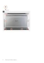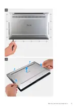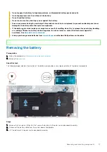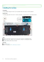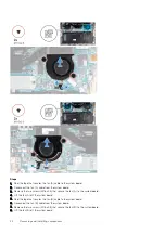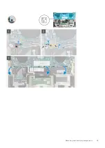
Steps
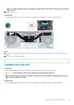
1. Align the screw holes on the heat sink with the screw holes on the system board.
2. In sequential order (as indicated on the heat sink), tighten the four captive screws that secure the heat sink to the system board.
Next steps
1. Install the
.
2. Follow the procedure in
After working inside your computer
.
Identifier
GUID-E641BD48-9062-46FE-8F5A-723887A0921D
Version
2
Status
Released
Display assembly
Identifier
GUID-4E7BE0FA-97BE-4C9E-96FF-8FB892551CA7
Version
1
Status
Released
Removing the display assembly
Prerequisites
1. Follow the procedure in
Before working inside your computer
.
2. Remove the
About this task
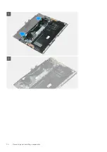
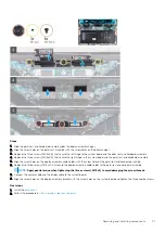
The following images indicate the location of the display assembly and provide a visual representation of the removal procedure.
26
Removing and installing components
Содержание XPS 13 9300
Страница 1: ...XPS 13 9300 Service Manual Regulatory Model P117G Regulatory Type P117G001 ...
Страница 12: ...12 Removing and installing components ...
Страница 13: ...Removing and installing components 13 ...
Страница 15: ...Removing and installing components 15 ...
Страница 27: ...Removing and installing components 27 ...
Страница 30: ...30 Removing and installing components ...
Страница 33: ...Removing and installing components 33 ...
Страница 53: ...3 The Bios flash menu will open then click the Flash from file 4 Select external USB device System setup 53 ...

