background image

Identifier

GUID-3C4573AB-7C32-4215-98B6-26F649510437

Version

1

Status

Released

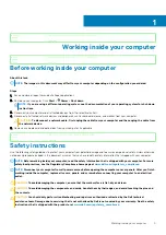
After working inside your computer

About this task

CAUTION: 

Leaving stray or loose screws inside your computer may severely damage your computer.

Steps

1. Replace all screws and ensure that no stray screws remain inside your computer.
2. Connect any external devices, peripherals, or cables you removed before working on your computer.
3. Replace any media cards, discs, or any other parts that you removed before working on your computer.
4. Connect your computer and all attached devices to their electrical outlets.
5. Turn on your computer.

8

Working inside your computer

Содержание XPS 13 9300

Страница 1: ...XPS 13 9300 Service Manual Regulatory Model P117G Regulatory Type P117G001 ...

Страница 2: ...N A CAUTION indicates either potential damage to hardware or loss of data and tells you how to avoid the problem WARNING A WARNING indicates a potential for property damage personal injury or death 2019 Dell Inc or its subsidiaries All rights reserved Dell EMC and other trademarks are trademarks of Dell Inc or its subsidiaries Other trademarks may be trademarks of their respective owners 2019 12 R...

Страница 3: ...y 17 Installing the battery 18 Solid state drive 19 Removing the solid state drive 19 Installing the solid state drive 20 Fans 21 Removing the fans 21 Installing the fans 23 Heat sink 24 Removing the heat sink 24 Installing the heat sink 25 Display assembly 26 Removing the display assembly 26 Installing the display assembly 29 System board 32 Removing the system board 32 Installing the system boar...

Страница 4: ...u 52 System and setup password 55 Assigning a system setup password 55 Deleting or changing an existing system setup password 56 Clearing CMOS settings 56 Clearing BIOS System Setup and System passwords 57 5 Troubleshooting 58 Recovering the operating system 58 Enhanced Pre Boot System Assessment ePSA diagnostics 58 Running the ePSA diagnostics 58 System diagnostic lights 59 Flea power release 60 ...

Страница 5: ...structions Use the following safety guidelines to protect your computer from potential damage and to ensure your personal safety Unless otherwise noted each procedure included in this document assumes that you have read the safety information that shipped with your computer NOTE Before working inside your computer read the safety information that is shipped with your computer For more safety best ...

Страница 6: ...POST No Video symptom with a beep code emitted for missing or nonfunctional memory Intermittent Intermittent failures represent approximately 80 percent of ESD related failures The high rate of intermittent failures means that most of the time when damage occurs it is not immediately recognizable The DIMM receives a static shock but the tracing is merely weakened and does not immediately produce o...

Страница 7: ...t can cause an ESD event On the work area insulators such as Styrofoam and other plastics should always be moved at least 12 inches or 30 centimeters away from sensitive parts before physically handling any hardware components ESD Packaging All ESD sensitive devices must be shipped and received in static safe packaging Metal static shielded bags are preferred However you should always return the d...

Страница 8: ...uter Steps 1 Replace all screws and ensure that no stray screws remain inside your computer 2 Connect any external devices peripherals or cables you removed before working on your computer 3 Replace any media cards discs or any other parts that you removed before working on your computer 4 Connect your computer and all attached devices to their electrical outlets 5 Turn on your computer 8 Working ...

Страница 9: ... storage box This is to ensure that the correct number of screws and correct screw type is restored when the component is replaced NOTE Some computers have magnetic surfaces Ensure that the screws are not left attached to such surface when replacing a component NOTE Screw color may vary with the configuration ordered Table 1 Screw list Component Secured to Screw type Quantity Screw image Base cove...

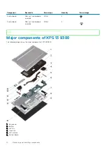
Страница 10: ...m rest and keyboard assembly M1 4x4 4 Identifier GUID 0926C03C 4EBE 4F12 A31F 73401FBAD8AD Version 1 Status Released Major components of XPS 13 9300 The following image shows the major components of XPS 13 9300 1 Base cover 2 Battery 3 Left fan 4 Heat sink 5 Left antenna 6 System board 10 Removing and installing components ...

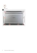
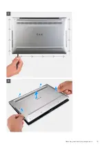
Страница 11: ...anty coverages purchased by the customer Contact your Dell sales representative for purchase options Identifier GUID 011AA877 0F90 479B BF50 6CDFB72AD6D8 Version 2 Status Released Base cover Identifier GUID 04115B43 677D 484F 87F6 A5482C9A0BA8 Version 1 Status Released Removing the base cover Prerequisites 1 Follow the procedure in Before working inside your computer About this task The following ...

Страница 12: ...12 Removing and installing components ...

Страница 13: ...Removing and installing components 13 ...

Страница 14: ...g the antennas and the audio board are fragile Place the base cover on a clean surface to avoid damage to the pins NOTE The following steps are applicable only if you want to further remove any other component from your computer 4 Using the pull tab disconnect the battery cable from the system board 5 Turn your computer over and press the power button for 15 seconds to drain the flea power Identif...

Страница 15: ...Removing and installing components 15 ...

Страница 16: ...g inside your computer Identifier GUID F65273B2 AF5E 4C69 B895 7CEF2148F79D Version 1 Status Released Battery Identifier GUID 22C7DCB3 8D29 41D7 8D51 D90ABC7C2D63 Version 10 Status Released Lithium ion battery precautions CAUTION Exercise caution when handling Lithium ion batteries Discharge the battery as much as possible before removing it from the system This can be done by disconnecting the AC...

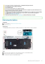
Страница 17: ...ance contact Dell technical support for assistance See www dell com contactdell Always purchase genuine batteries from www dell com or authorized Dell partners and resellers Identifier GUID BD851266 44A4 437D 96D9 A3467C107121 Version 1 Status Released Removing the battery Prerequisites 1 Follow the procedure in Before working inside your computer 2 Remove the base cover About this task The follow...

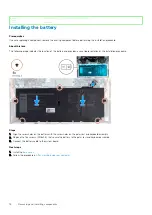
Страница 18: ...location of the battery and provides a visual representation of the installation procedure Steps 1 Align the screw holes on the battery with the screw holes on the palm rest and keyboard assembly 2 Replace the five screws M1 6x2 5 that secure the battery to the palm rest and keyboard assembly 3 Connect the battery cable to the system board Next steps 1 Install the base cover 2 Follow the procedure...

Страница 19: ...ON Solid state drives are fragile Exercise care when handling the solid state drive CAUTION To avoid data loss do not remove the solid state drive while the computer is in sleep or on state 2 Remove the base cover About this task The following image indicates the location of the solid state drive and provides a visual representation of the removal procedure Steps 1 Loosen the captive screw that se...

Страница 20: ...state drive from the solid state drive slot NOTE The size of the solid state drive shield is specific to the size of the solid state drive that is shipped with your computer The solid state drive shield cannot be used for a different sized solid state drive Identifier GUID 903A2731 533D 428B 8AD3 89B45DE7B0A3 Version 1 Status Released Installing the solid state drive Prerequisites If you are repla...

Страница 21: ...ystem board toward the wireless card 6 Connect the antenna cables to the wireless card 7 Align the screw hole on the wireless card bracket with the screw hole on the system board NOTE Ensure that tab on the wireless card bracket is inserted into the slot in the system board 8 Tighten the captive screw that secures the wireless card bracket to the system board Next steps 1 Install the base cover 2 ...

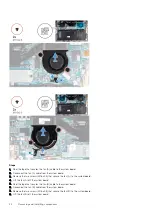
Страница 22: ...x2 5 that secure the fan A to the system board 4 Lift the fan A off the system board 5 Peel the tape that secures the fan B cable to the system board 6 Disconnect the fan B cable from the system board 7 Remove the two screws M1 6x2 5 that secure the fan B to the system board 8 Lift the fan B off the system board 22 Removing and installing components ...

Страница 23: ...s Prerequisites If you are replacing a component remove the existing component before performing the installation procedure About this task The following images indicate the location of the fans and provide a visual representation of the installation procedure Removing and installing components 23 ...

Страница 24: ...stem board 8 Adhere the tape that secures the fan A cable to the system board Next steps 1 Install the base cover 2 Follow the procedure in After working inside your computer Identifier GUID 4DA6FA84 FF63 4D31 A148 125AAD9F4B2B Version 1 Status Released Heat sink Identifier GUID A837597B 2FB9 4804 AE1E B059B086720D Version 1 Status Released Removing the heat sink Prerequisites 1 Follow the procedu...

Страница 25: ...system board Identifier GUID 41D199E0 56B2 459A 9E9A 54B0C3AA36BD Version 1 Status Released Installing the heat sink Prerequisites If you are replacing a component remove the existing component before performing the installation procedure CAUTION Incorrect alignment of the heat sink can damage the system board and processor NOTE If either the system board or the heat sink is replaced use the therm...

Страница 26: ... your computer Identifier GUID E641BD48 9062 46FE 8F5A 723887A0921D Version 2 Status Released Display assembly Identifier GUID 4E7BE0FA 97BE 4C9E 96FF 8FB892551CA7 Version 1 Status Released Removing the display assembly Prerequisites 1 Follow the procedure in Before working inside your computer 2 Remove the base cover About this task The following images indicate the location of the display assemb...

Страница 27: ...Removing and installing components 27 ...

Страница 28: ...display assembly cable holder to the palm rest and keyboard assembly 5 Remove the three screws M2 5x4 5 that secure the left hinge to the system board and the palm rest and keyboard assembly 6 Remove the three screws M2 5x4 5 that secure the right hinge to the system board and the palm rest and keyboard assembly 7 Slide the palm rest and keyboard assembly from the display assembly 8 After performi...

Страница 29: ...y Prerequisites If you are replacing a component remove the existing component before performing the installation procedure About this task The following images indicate the location of the display assembly and provide a visual representation of the installation procedure Removing and installing components 29 ...

Страница 30: ...30 Removing and installing components ...

Страница 31: ... the display assembly cable holder with the screw holes on the palm rest and keyboard assembly 6 Replace the three screws M1 2x2 that secure the display assembly cable holder to the palm rest and keyboard assembly NOTE Apply gentle torque when tightening the three screws M1 2x2 to avoid damaging the screw threads 7 Connect the camera cable and the display cable to the system board 8 Align the scre...

Страница 32: ...propriate changes again after you replace the system board NOTE Before disconnecting the cables from the system board note the location of the connectors so that you can reconnect the cables correctly after you replace the system board 2 Remove the base cover 3 Remove the battery 4 Remove the fans 5 Remove the heat sink NOTE The system board can be removed or installed together with the heat sink ...

Страница 33: ...Removing and installing components 33 ...

Страница 34: ...e system board 7 Disconnect the right speaker cable from the system board 8 Open the latch and disconnect the keyboard cable from the system board 9 Open the latch and disconnect the touchpad cable from the system board 10 Disconnect the left speaker cable from the system board 11 Remove the four screws M1 6x1 5 that secure the system board to the palm rest and keyboard assembly 12 Remove the thre...

Страница 35: ...the system board You must enter the Service Tag in the BIOS setup program after you replace the system board NOTE Replacing the system board removes any changes you have made to the BIOS using the BIOS setup program You must make the appropriate changes again after you replace the system board About this task The following images indicate the location of the system board and provide a visual repre...

Страница 36: ...r cable to the system board 7 Connect the keyboard cable to the system board and close the latch to secure the cable 8 Connect the touchpad cable to the system board and close the latch to secure the cable 9 Connect the left speaker cable to the system board 10 Route the left and right antenna cables through the routing guides on the palm rest and keyboard assembly toward the wireless card 11 Conn...

Страница 37: ...DEC AD46B79B8EA6 Version 2 Status Released Palm rest and keyboard assembly Identifier GUID E3DDE5C6 EA6C 4047 941F 6F1B51F1CC21 Version 1 Status Released Removing the palm rest and keyboard assembly Prerequisites 1 Follow the procedure in Before working inside your computer 2 Remove the base cover 3 Remove the battery 4 Remove the display assembly 5 Remove the system board About this task The foll...

Страница 38: ...procedure About this task The following image indicates the palm rest and keyboard assembly and provides a visual representation of the installation procedure Steps Place the palm rest and keyboard assembly on a flat surface Next steps 1 Install the system board 2 Install the display assembly 3 Install the battery 4 Install the base cover 5 Follow the procedure in After working inside your compute...

Страница 39: ...1B8A47E387E Version 1 Status Released Drivers and downloads When troubleshooting downloading or installing drivers it is recommended that you read the Dell Knowledge Based article Drivers and Downloads FAQ SLN128938 3 Drivers and downloads 39 ...

Страница 40: ... type of hard drive installed and enabling or disabling base devices Identifier GUID DACDEF92 BD0F 40C4 B280 5E81EB67A4C5 Version 1 Status Released Entering BIOS setup program Steps 1 Turn on your computer 2 Press F2 immediately to enter the BIOS setup program NOTE If you wait too long and the operating system logo appears continue to wait until you see the desktop Then turn off your computer and ...

Страница 41: ... access the System Setup screen Identifier GUID CC110EA9 65ED 4FF8 BB35 7C2853FFB988 Version 1 Status Released System setup options NOTE Depending on this computer and its installed devices the items that are listed in this section may or may not be displayed Table 3 System setup options System information menu Overview XPS 13 9300 BIOS Version Displays the BIOS version number Service Tag Displays...

Страница 42: ...or dual channel mode Memory Technology Displays the technology that is used for the memory DEVICES Panel Type Displays the Panel Type of the computer Video Controller Displays the integrate graphics information of the computer Video Memory Displays the video memory information of the computer Wi Fi Device Displays the Wi Fi device installed in the computer Native Resolution Displays the native res...

Страница 43: ...gy SMART Default OFF Enable Audio Enables or disables all integrated audio controller Default ON Enable Microphone Enables or disables microphone By default Enable Microphone is selected Enable Internal Speaker Enables or disables internal speaker By default Enable Internal Speaker is selected USB Configuration Enables or disables booting from USB mass storage devices such as external hard drive o...

Страница 44: ... Table 6 System setup options Video menu Video LCD Brightness Brightness on battery power Sets the screen brightness when the computer is running on battery power Default 50 Brightness on AC power Sets the screen brightness when the computer is running on AC power Default 100 Table 7 System setup options Security menu Security Enable Admin Setup Lockout Enables or disables the user from entering B...

Страница 45: ...easurements into the TPM PCRs during BIOS boot Default ON Clear Enables or disables the computer to clear the PTT owner information and returns the PTT to the default state Default OFF TPM State Enables or disables the TPM This is the normal operating state for the TPM when you want to use its complete array of capabilities Default Enabled SMM Security Mitigation Enables or disables additional UEF...

Страница 46: ...t Key Management menu Expert Key Management Enable Custom Mode Enables or disables the keys in the PK KEK db and dbx security key databases to be modified Default OFF Custom Mode Key Management Selects the custom values for expert key management Default PK Table 11 System setup options Performance menu Performance Multi Core Support Active Cores Changes the number of CPU cores available to the ope...

Страница 47: ...ng power usage hours Use the below options to prevent AC power usage between certain times of each day Default Adaptive Battery settings are adaptively optimized based on your typical battery usage pattern Enable Advanced Battery Charge Configuration Enables Advanced Battery Charge Configuration from the beginning of the day to a specified work period Advanced Battery Charged maximizes battery hea...

Страница 48: ...the operation of the computer hardware will always halt the computer Enable Adapter Warnings Enables or disables the computer to display adapter warning messages when adapters with too little power capacity are detected Default ON Enable Dock Warning Messages Enables or disables dock warning messages Default ON Fastboot Configures the speed of the UEFI boot process Default Thorough Performs comple...

Страница 49: ...OS image as long as the Boot Block portion is intact and functioning Default ON NOTE BIOS recovery is designed to fix the main BIOS block and cannot work if the Boot Block is damaged In addition this feature cannot work in the event of EC corruption ME corruption or a hardware issue The recovery image must exist on an unencrypted partition on the drive BIOS Auto Recovery Enables the computer to au...

Страница 50: ...e the system board or if an update is available For laptops ensure that your computer battery is fully charged and connected to a power outlet About this task NOTE If BitLocker is enabled it must be suspended prior to updating the system BIOS and then re enabled after the BIOS update is completed Steps 1 Restart the computer 2 Go to Dell com support Enter the Service Tag or Express Service Code an...

Страница 51: ...atus Released Updating your system BIOS using a USB flash drive About this task If the system cannot load into Windows but there is still a need to update the BIOS download the BIOS file using another system and save it to a bootable USB Flash Drive NOTE You will need to use a bootable USB Flash drive Please refer to the following article for further details https www dell com support article sln1...

Страница 52: ... as a boot option for your system If the option is listed then the BIOS supports this BIOS update option NOTE Only systems with BIOS Flash Update option in the F12 One Time Boot Menu can use this function Updating from the One Time Boot Menu To update your BIOS from the F12 One Time boot menu you will need USB key formatted to the FAT32 file system key does not have to be bootable BIOS executable ...

Страница 53: ...3 The Bios flash menu will open then click the Flash from file 4 Select external USB device System setup 53 ...

Страница 54: ...5 Once the file is selected Double click the flash target file then press submit 6 Click the Update BIOS then system will reboot to flash the BIOS 54 System setup ...

Страница 55: ...rd to secure your computer CAUTION The password features provide a basic level of security for the data on your computer CAUTION Anyone can access the data that is stored on your computer if it is not locked and left unattended NOTE System and setup password feature is disabled Identifier GUID 84D45A70 0C01 4677 B066 55414B65F122 Version 1 Status Released Assigning a system setup password Prerequi...

Страница 56: ...mediately after a power on or reboot Steps 1 In the System BIOS or System Setup screen select System Security and press Enter The System Security screen is displayed 2 In the System Security screen verify that Password Status is Unlocked 3 Select System Password alter or delete the existing system password and press Enter or Tab 4 Select Setup Password alter or delete the existing setup password a...

Страница 57: ...OS System Setup and System passwords About this task To clear the system or BIOS passwords contact Dell technical support as described at www dell com contactdell NOTE For information on how to reset Windows or application passwords refer to the documentation accompanying Windows or your application System setup 57 ...

Страница 58: ...ecovery see Dell SupportAssist OS Recovery User s Guide at www dell com support Identifier GUID EE9A5D95 88BE 4EE7 983E D97C680BDECD Version 5 Status Released Enhanced Pre Boot System Assessment ePSA diagnostics About this task The ePSA diagnostics also known as system diagnostics performs a complete check of your hardware The ePSA is embedded with the BIOS and is launched by the BIOS internally T...

Страница 59: ...ht Table 20 Power and battery charge status light Power and battery charge status light Status of computer Solid white The power adapter is connected and the battery is fully charged The power adapter is connected and the battery has more than 5 percent charge Amber The computer is running on battery and the battery has less than 5 percent charge Off The computer is in sleep state hibernation or t...

Страница 60: ...ff your computer 2 Remove the base cover NOTE The battery must be disconnected from the system board see Step 4 in Removing the base cover 3 Press and hold the power button for 15 seconds to drain the flea power 4 Install the base cover 5 Turn on your computer Identifier GUID 7D2143EA 2C62 498E 97AF DCEF3DA56624 Version 5 Status Released WiFi power cycle About this task If your computer is unable ...

Страница 61: ...he Search box 3 Click Search to retrieve the related articles Learn and know the following information about your product Product specifications Operating system Setting up and using your product Data backup Troubleshooting and diagnostics Factory and system restore BIOS information See Me and My Dell at www dell com support manuals To locate the Me and My Dell relevant to your product identify yo...

Отзывы: