background image

Steps

1. Peel the fingerprint reader cable from the keyboard.
2. Remove the speaker cable from the routing guides on the left keyboard bracket.
3. Loosen the captive screw that secures the left keyboard bracket to the palm-rest assembly.
4. Using a plastic scribe, pry the left keyboard bracket off the palm-rest assembly.
5. Loosen the captive screw that secures the right keyboard bracket to the palm-rest assembly.
6. Using a plastic scribe, pry the right keyboard bracket off the palm-rest assembly.
7. Disconnect the keyboard cable and keyboard backlight cable from the keyboard controller board.
8. Peel the keyboard controller board cable from the keyboard.
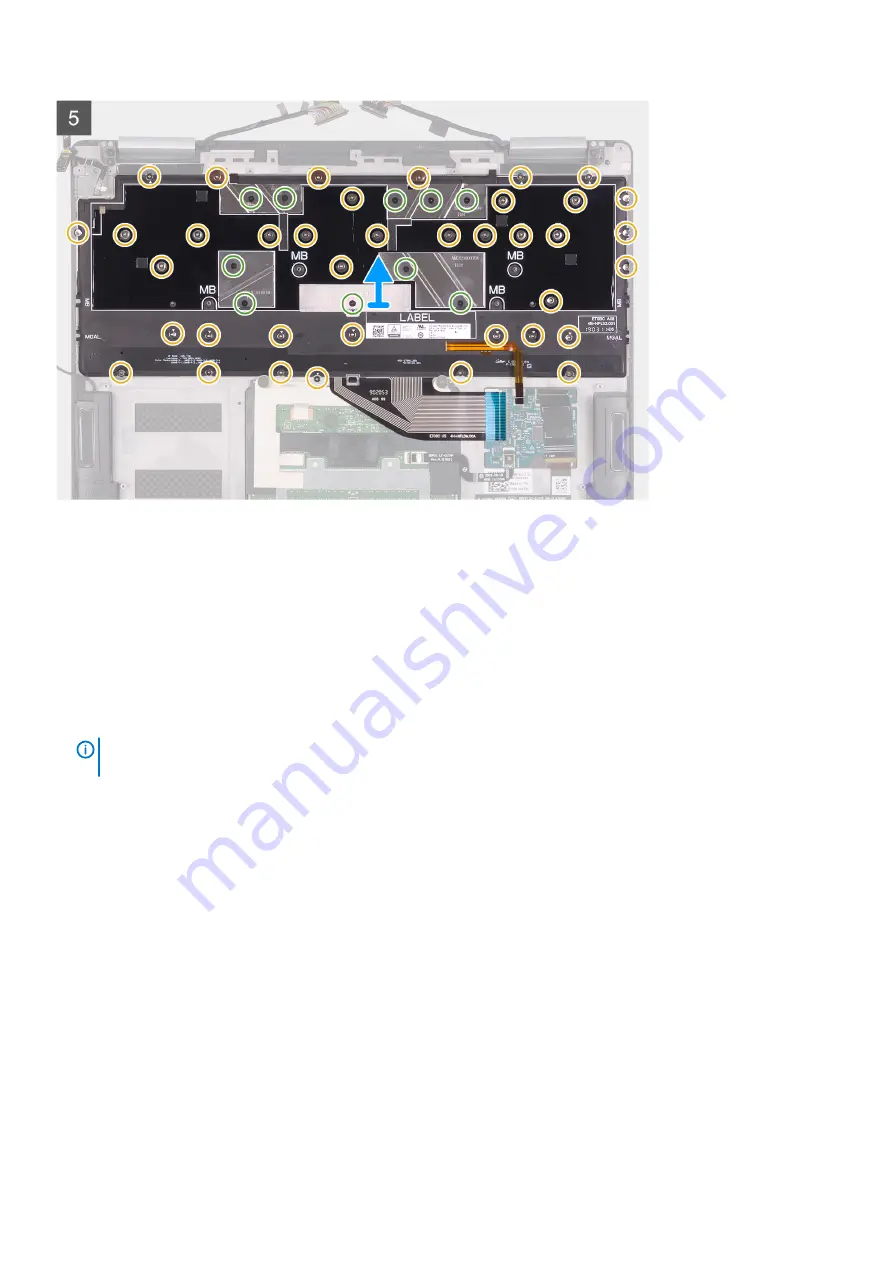
9. Remove the 38 screws (M1.2x1.4) and ten screws (M1.2x1.6) that secure the keyboard to the palm-rest assembly.

NOTE: 

Peel off the three copper foil from the palm-rest assembly, and then peel off the two conductive tapes on the 

keyboard assembly to separate the keyboard assembly and the palm-rest assembly.

10. Lift the keyboard off the palm-rest assembly.

Installing the Keyboard

Prerequisites

If you are replacing a component, remove the existing component before performing the installation procedure.

About this task

The following images indicate the location of keyboard assembly and provide a visual representation of the installation procedure.

28

Removing and installing components

Содержание XPS 13 7390 2-in-1

Страница 1: ...XPS 13 7390 2 in 1 Service Manual Regulatory Model P103G Regulatory Type P103G001 ...

Страница 2: ...amage to hardware or loss of data and tells you how to avoid the problem WARNING A WARNING indicates a potential for property damage personal injury or death 2019 Dell Inc or its subsidiaries All rights reserved Dell EMC and other trademarks are trademarks of Dell Inc or its subsidiaries Other trademarks may be trademarks of their respective owners 2019 06 Rev A00 ...

Страница 3: ...nstalling the display assembly 18 Speakers 20 Removing the speakers 20 Installing the speakers 21 System board assembly 21 Removing the system board 21 Installing the system board 24 Keyboard assembly 27 Removing the keyboard assembly 27 Installing the Keyboard 28 Palm rest assembly 31 Removing the palm rest and keyboard assembly 31 Installing the palm rest assembly 31 3 Device drivers 33 Intel Ch...

Страница 4: ...ring CMOS settings 45 Clearing BIOS System Setup and System passwords 45 5 Troubleshooting 46 Enhanced Pre Boot System Assessment ePSA diagnostics 46 Running the ePSA diagnostics 46 Recovering the operating system 46 Flashing BIOS USB key 47 Flashing the BIOS 47 Backup media and recovery options 47 WiFi power cycle 47 Flea power release 48 6 Getting help and contacting Dell 49 4 Contents ...

Страница 5: ...computer While you work periodically touch an unpainted metal surface to dissipate static electricity which could harm internal components CAUTION When you disconnect a cable pull on its connector or on its pull tab not on the cable itself Some cables have connectors with locking tabs or thumb screws that you must disengage before disconnecting the cable When disconnecting cables keep them evenly ...

Страница 6: ... sensitive component place it in an anti static container or packaging ESD field service kit The unmonitored Field Service kit is the most commonly used service kit Each Field Service kit includes three main components anti static mat wrist strap and bonding wire Components of an ESD field service kit The components of an ESD field service kit are Anti Static Mat The anti static mat is dissipative...

Страница 7: ...Dell products In addition it is critical that technicians keep sensitive parts separate from all insulator parts while performing service and that they use anti static bags for transporting sensitive components Transporting sensitive components When transporting ESD sensitive components such as replacement parts or parts to be returned to Dell it is critical to place these parts in anti static bag...

Страница 8: ...e computers have magnetic surfaces Ensure that the screws are not left attached to such surface when replacing a component NOTE Screw color may vary with the configuration ordered Table 1 Screw list Component Secured to Screw type Quantity Screw image Base cover Palm rest assembly M2x4 5 8 Torx screws Battery System board M1 6x3 4 1 Torx screw Battery Palm rest assembly M1 6x3 7 Battery Palm rest ...

Страница 9: ...y Palm rest assembly M1 2x1 4 38 Keyboard assembly Palm rest assembly M1 2x1 6 10 Base cover Removing the base cover Prerequisites 1 Follow the procedure in Before working inside your computer About this task The following images indicate the location of the base cover and provide a visual representation of the removal procedure Removing and installing components 9 ...

Страница 10: ...10 Removing and installing components ...

Страница 11: ...Removing and installing components 11 ...

Страница 12: ...otate from front to back to remove from palm rest assembly NOTE The pins at the bottom of the base cover for grounding the antennas and the audio board are fragile Place the base cover on a clean surface to avoid damage to the pins Installing the base cover Prerequisites If you are replacing a component remove the existing component before performing the installation procedure About this task The ...

Страница 13: ...palm rest assembly Next steps 1 Follow the procedure in After working inside your computer Battery Removing the battery Prerequisites 1 Follow the procedure in Before working inside your computer 2 Remove the base cover About this task The following image indicates the location of the battery and provides a visual representation of the removal procedure Removing and installing components 13 ...

Страница 14: ...stem board 2 Disconnect the battery cable from the interposer board NOTE Remove the interposer board immediately after disconnecting the battery cable to avoid misplacing it Hold the edges of the interposer board to avoid damaging the pins on it 14 Removing and installing components ...

Страница 15: ... assembly 7 Turn the battery over 8 Using a plastic scribe push to remove the magnet and the metal bar from the battery NOTE Keep the magnet and the metal bar as they need to be installed on the new battery Installing the battery Prerequisites If you are replacing a component remove the existing component before performing the installation procedure About this task The following image indicates th...

Страница 16: ... The interposer board is not polarity sensitive and both sides are compatible 6 Connect the battery cable to the interposer board 7 Replace the Torx 5 screw M1 6x3 4 that secures the battery cable to the system board Next steps 1 Install the base cover 2 Follow the procedure in After working inside your computer Display assembly Removing the display assembly Prerequisites 1 Follow the procedure in...

Страница 17: ...system board 2 Lift the display cable bracket off the system board 3 Peel the tapes that secure the display cable and camera cable to the system board 4 Using the tape as a pull tab disconnect the display cable and camera cable from the system board Removing and installing components 17 ...

Страница 18: ... the palm rest assembly off the display assembly Installing the display assembly Prerequisites If you are replacing a component remove the existing component before performing the installation procedure About this task The following images indicate the location of display assembly and provide a visual representation of the installation procedure 18 Removing and installing components ...

Страница 19: ...s on the palm rest assembly with the screw holes on the display hinges 3 Replace the four screws M2 5x3 that secure the display hinges to the palm rest assembly 4 Route the display cable and camera cable through the routing guides on the system board Removing and installing components 19 ...

Страница 20: ... working inside your computer Speakers Removing the speakers Prerequisites 1 Follow the procedure in Before working inside your computer 2 Remove the base cover 3 Remove the battery About this task The following image indicates the location of speakers and provides a visual representation of the removal procedure Steps 1 Disconnect the speaker cable from the system board 2 Note the routing of the ...

Страница 21: ...Ensure that there is no adhesive residue from the faulty speakers that are removed previously 2 Route the speaker cable through the routing guides on the palm rest and keyboard assembly 3 Connect the speaker cable to the system board Next steps 1 Install the battery 2 Install the base cover 3 Follow the procedure in After working inside your computer System board assembly Removing the system board...

Страница 22: ...1 System board connectors 1 Speaker cable 2 Fingerprint reader cable 3 Display cable 4 Camera cable 5 Keyboard controller board cable The following images indicate the location of system board and provide a visual representation of the removal procedure 22 Removing and installing components ...

Страница 23: ...ures the type C bracket to the system board NOTE The M1 6x2 screw has a bigger head than the M1 6x3 screw 7 Lift the type C bracket off the system board 8 Disconnect the speaker cable from the system board 9 Open the latch and disconnect the fingerprint reader cable from the system board 10 Peel off the fingerprint reader daughter board from the system board 11 Open the latch and disconnect the ke...

Страница 24: ...he following image indicates the connectors on your system board Figure 2 System board connectors 1 Speaker cable 2 Fingerprint reader cable 3 Display cable 4 Camera cable 5 Keyboard controller board cable The following images indicate the location of system board and provide a visual representation of the installation procedure 24 Removing and installing components ...

Страница 25: ...Removing and installing components 25 ...

Страница 26: ...Type C bracket to the screw holes on the system board 8 Replace the screw M1 6x3 and the screw M1 6x2 that secures the USB Type C port bracket to the system board NOTE The M1 6x2 screw has a bigger head than the M1 6x3 screw 9 Route the display cable and camera cable through the routing guides on the system board 10 Connect the display cable and camera cable to the system board 11 Adhere the tapes...

Страница 27: ...fore working inside your computer 2 Remove the base cover 3 Remove the battery 4 Remove the system board assembly About this task The following images indicate the location of keyboard assembly and provide a visual representation of the removal procedure Removing and installing components 27 ...

Страница 28: ...eyboard controller board 8 Peel the keyboard controller board cable from the keyboard 9 Remove the 38 screws M1 2x1 4 and ten screws M1 2x1 6 that secure the keyboard to the palm rest assembly NOTE Peel off the three copper foil from the palm rest assembly and then peel off the two conductive tapes on the keyboard assembly to separate the keyboard assembly and the palm rest assembly 10 Lift the ke...

Страница 29: ...Removing and installing components 29 ...

Страница 30: ... keyboard 4 Connect the keyboard cable and keyboard backlight cable to the keyboard controller board 5 Adhere the right keyboard bracket in the slots on the palm rest assembly 6 Tighten the captive screw that secures the right keyboard bracket to the palm rest assembly 7 Adhere the right keyboard bracket in the slots on the palm rest assembly 8 Tighten the captive screw that secures the left keybo...

Страница 31: ...rovides a visual representation of the removal procedure Steps After performing the steps in the prerequisites we are left with the palm rest assembly NOTE Keep the power button bracket if you need to replace the palm rest assembly as it is reusable Installing the palm rest assembly Prerequisites If you are replacing a component remove the existing component before performing the installation proc...

Страница 32: ...r button bracket from the previous palm rest assembly Next steps 1 Install the keyboard assembly 2 Install the system board assembly 3 Install the speakers 4 Install the display assembly 5 Install the battery 6 Install the base cover 7 Follow the procedure in After working inside your computer 32 Removing and installing components ...

Страница 33: ...l com support Intel Trusted Execution Engine Interface In the Device Manager check if the Intel Trusted Execution Engine Interface driver is installed Install the driver update from www dell com support Intel Virtual Button driver In the Device Manager check if the Intel Virtual Button driver is installed Install the driver updates from www dell com support Wireless and Bluetooth drivers In the De...

Страница 34: ...perating system and attached devices such as hard disk video adapter keyboard mouse and printer Entering BIOS setup program Steps 1 Turn on or restart your computer 2 During POST when the DELL logo is displayed watch for the F2 prompt to appear and then press F2 immediately NOTE The F2 prompt indicates that the keyboard is initialized This prompt can appear very quickly so you must watch for it an...

Страница 35: ...he option to access the System Setup screen System setup options NOTE Depending on this computer and its installed devices the items that are listed in this section may or may not be displayed Table 2 System setup options System information menu Overview BIOS Version Displays the BIOS version number Service Tag Displays the Service Tag of the computer Asset Tag Displays the Asset Tag of the comput...

Страница 36: ...troller Displays the integrate graphics information of the computer Video BIOS Version Displays the video BIOS version of the computer Video Memory Displays the video memory information of the computer Panel Type Displays the Panel Type of the computer Native Resolution Displays the native resolution of the computer Audio Controller Displays the audio controller information of the computer Wi Fi D...

Страница 37: ...egrated audio controller Default ON Enable Microphone Enables or disables microphone Default ON Enable Internal Speaker Enables or disables internal speaker Default ON USB Configuration Enable Boot Support Enables or disables booting from USB mass storage devices such as external hard drive optical drive and USB drive Default ON Enable External USB Ports Enables or disables USB ports to be functio...

Страница 38: ...ery power Sets the screen brightness when the computer is running on battery power Brightness on AC power Sets the screen brightness when the computer is running on AC power Table 6 System setup options Security menu Security Enable Admin Setup Lockout Enables or disables the user from entering BIOS Setup when an Admin Password is set Default OFF Password Bypass Bypass the System Boot Password and...

Страница 39: ...ments into the TPM PCRs during BIOS boot Default ON Clear Enables or disables the computer to clear the PTT owner information and returns the PTT to the default state Default OFF TPM State Enables or disables the TPM This is the normal operating state for the TPM when you want to use its complete array of capabilities Default Enabled Intel SGX Enables or disables the Intel Software Guard Extension...

Страница 40: ...les the Intel Hyper Threading Technology to use processor resources more efficiently Default ON Intel SpeedStep Enables or disables the Intel SpeedStep Technology to dynamically adjust processor voltage and core frequency decreasing average power consumption and heat production Default ON Intel TurboBoost Technology Enabled or disabled the Intel TurboBoost mode of the processor If enabled the Inte...

Страница 41: ...ft Enables the computer to run on battery during peak power usage hours Default OFF Wireless Radio Control Enables to sense the connection of the computer to a wired network and subsequently disable the selected wireless radios WLAN and or WWAN Upon disconnection from the wired network the selected wireless radios are re enabled Default OFF Wake on LAN Enables or disables the computer to turn on b...

Страница 42: ...ow the computer handles mouse and touchpad input Default Touchpad and PS 2 Mouse Leave the integrated touchapd enabled when an external PS 2 mouse is present Sign of Life Early Logo Display Display Logo Sign of Life Default ON Early Keyboard Backlight Keyboard Backlight Sign of Life Default ON MAC Address Pass Through Replaces the external NIC MAC address in a supported dock or dongle with the sel...

Страница 43: ...llow BIOS Downgrade Controls flashing of the system firmware to previous revisions Default ON Table 15 System setup options System Logs menu System Logs Power Event Log Displays Power events Default Keep BIOS Event Log Displays BIOS events Default Keep Thermal Event Log Displays Thermal events Default Keep Table 16 System setup options SupportAssist menu SupportAssist Dell Auto operating system Re...

Страница 44: ...d click OK 4 Press Esc and a message prompts you to save the changes 5 Press Y to save the changes The computer reboots Deleting or changing an existing system setup password Prerequisites Ensure that the Password Status is Unlocked in the System Setup before attempting to delete or change the existing System and or Setup password You cannot delete or change an existing System or Setup password if...

Страница 45: ...one minute 4 Connect the battery cable to the system board 5 Replace the base cover Clearing BIOS System Setup and System passwords About this task To clear the system or BIOS passwords contact Dell technical support as described at www dell com contactdell NOTE For information on how to reset Windows or application passwords refer to the documentation accompanying Windows or your application Syst...

Страница 46: ...the bottom left corner Diagnostics front page is displayed 5 Click the arrow in the lower right corner to go to the page listing The items detected are listed 6 To run a diagnostic test on a specific device press Esc and click Yes to stop the diagnostic test 7 Select the device from the left pane and click Run Tests 8 If there are any issues error codes are displayed Note the error code and valida...

Страница 47: ... the Service Tag use the auto detect feature or manually browse for your computer model 4 Click Drivers downloads Find it myself 5 Select the operating system installed on your computer 6 Scroll down the page and expand BIOS 7 Click Download to download the latest version of the BIOS for your computer 8 After the download is complete navigate to the folder where you saved the BIOS update file 9 Do...

Страница 48: ... after it has been powered off and the battery has been removed The following procedure provides the instructions on how to conduct flea power release Steps 1 Turn off your computer 2 Remove the base cover 3 Remove the battery 4 Press and hold the power button for 15 seconds to drain the flea power 5 Replace the battery 6 Replace the base cover 7 Turn on your computer 48 Troubleshooting ...

Страница 49: ... the related articles Learn and know the following information about your product Product specifications Operating system Setting up and using your product Data backup Troubleshooting and diagnostics Factory and system restore BIOS information See Me and My Dell at www dell com support manuals To locate the Me and My Dell relevant to your product identify your product through one of the following ...

Отзывы: