


2. Replace the two (M2x2) screws that secure the display hinges to the display back-cover.
3. Replace the four (M2.5x2.5) screws to secure the display hinges to the display back-cover.
1. Install the
2. Install the
3. Install the
.
4. Install the
.
5. Install the
.
6. Follow the procedure in
After working inside your computer
.
Camera
Removing the camera
1. Follow the procedure in
Before working inside your computer
.
2. Remove the
3. Remove the
.
4. Remove the
5. Remove the
.
6. Remove the
.
7. Remove the
.
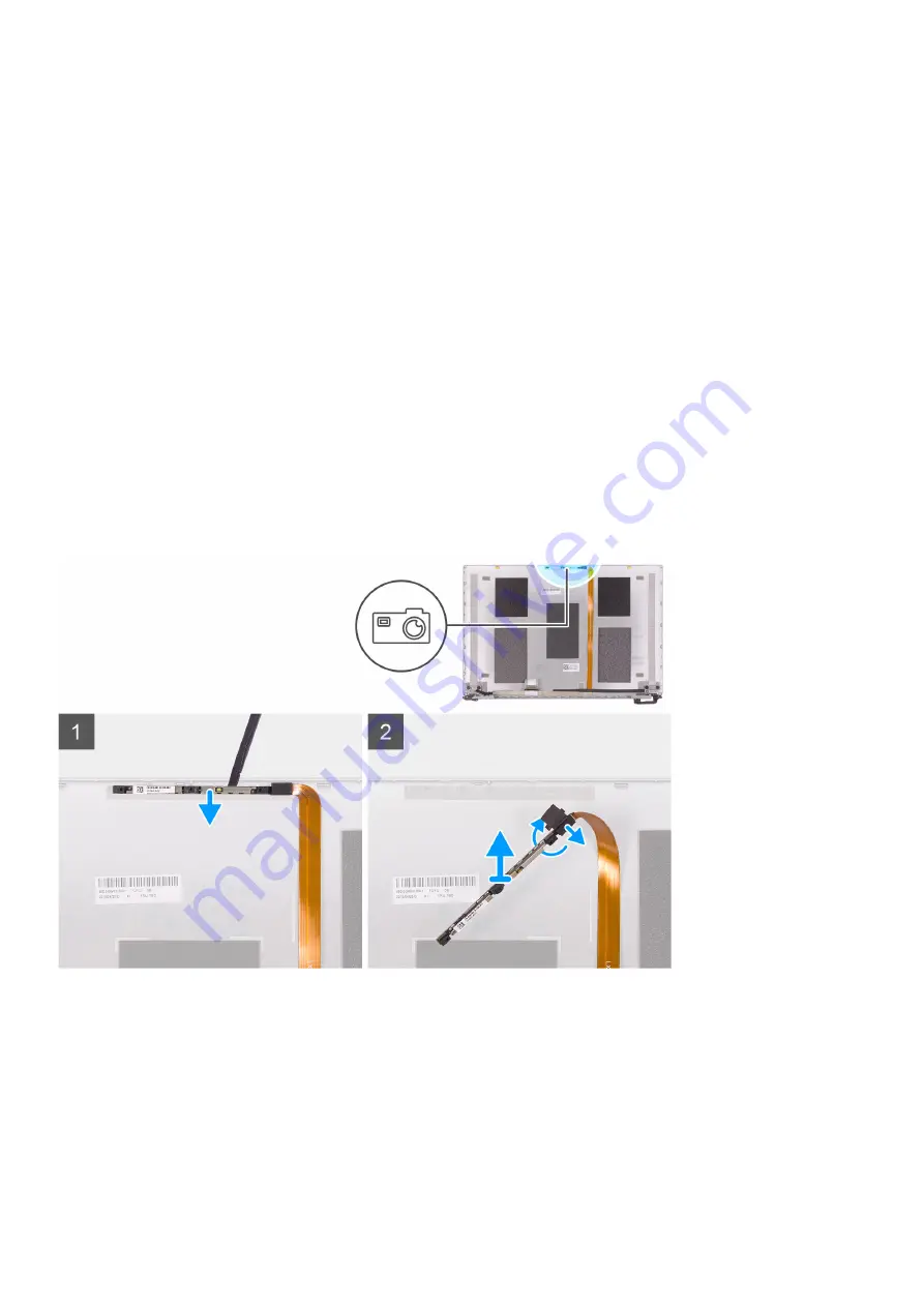
The following image indicates the location of camera and provides a visual representation of the removal procedure.
1. Using a plastic scribe, pry the camera from the alignment post on the display back-cover.
2. Turn over the camera and disconnect the camera cable off the camera.
3. Peel the tape off the camera and lift the camera off the display back-cover.
Installing the camera
If you are replacing a component, remove the existing component before performing the installation procedure.
The following image indicates the location of camera and provides a visual representation of the installation procedure.
56
Removing and installing components
Содержание Vostro 5391
Страница 1: ...Dell Vostro 5391 Service Manual Regulatory Model P114G Regulatory Type P114G001 ...
Страница 33: ...Removing and installing components 33 ...
Страница 43: ...Removing and installing components 43 ...
Страница 45: ...Removing and installing components 45 ...
Страница 51: ...Removing and installing components 51 ...
Страница 53: ...Removing and installing components 53 ...


