


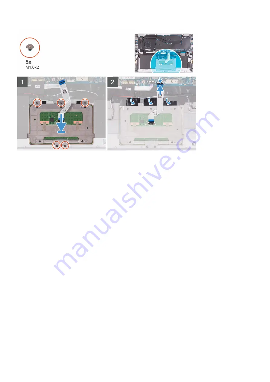
1. Align and place the touchpad into the slot on the palm-rest and keyboard assembly.
2. Replace the two (M1.6x2) screws that secure the touchpad to the palm-rest and keyboard assembly.
3. Align and place the touchpad bracket into the slot on the palm-rest and keyboard assembly.
4. Replace the three (M1.6x2) screws that secure the touchpad bracket to the palm-rest and keyboard assembly.
5. Slide the touchpad cable into its connector on the system board and close the latch to secure the cable.
6. Adhere the tape that secures the touchpad to the palm-rest and keyboard assembly.
1. Install the
.
2. Install the
.
3. Follow the procedure in
After working inside your computer
.
Display assembly
Removing the display assembly
1. Follow the procedure in
Before working inside your computer
.
2. Remove the
3. Remove the
.
The following image indicates the location of display assembly and provides a visual representation of the removal procedure.
32
Removing and installing components
Содержание Vostro 5391
Страница 1: ...Dell Vostro 5391 Service Manual Regulatory Model P114G Regulatory Type P114G001 ...
Страница 33: ...Removing and installing components 33 ...
Страница 43: ...Removing and installing components 43 ...
Страница 45: ...Removing and installing components 45 ...
Страница 51: ...Removing and installing components 51 ...
Страница 53: ...Removing and installing components 53 ...


