background image

Steps

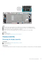
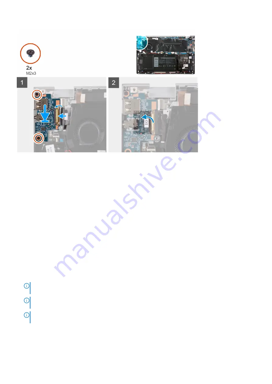
1. Align and place the I/O board on the palm-rest and keyboard assembly.
2. Replace the two screws (M2x3) that secure the I/O board to the palm-rest and keyboard assembly.
3. Connect the I/O-board cable and close the latch to secure the cable to the I/O board.
4. Adhere the tape that secures the I/O-board cable to the fan.
5. Adhere the tape that secures the I/O-board cable to the I/O board.

Next steps

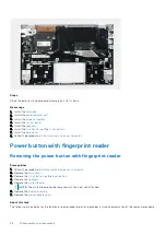
1. Install the 

fan

.

2. Install the 

base cover

.

3. Follow the procedure in 

After working inside your computer

.

System board

Removing the system board

Prerequisites

1. Follow the procedure in 

Before working inside your computer

.

NOTE:

 Your computer’s Service Tag is stored in the system board. You must enter the Service Tag in the BIOS setup

program after you replace the system board.

NOTE:

 Replacing the system board removes any changes you have made to the BIOS using the BIOS setup program.

You must make the appropriate changes again after you replace the system board.

NOTE:

 Before disconnecting the cables from the system board, note the location of the connectors so that you can

reconnect the cables correctly after you replace the system board.

2. Remove the 

base cover

.

3. Remove the 

4-cell battery

 or the 

2-cell battery

.

4. Remove the 

fan

.

5. Remove the 

heat sink

.

Disassembly and reassembly

39

Содержание Vostro 5301

Страница 1: ...Vostro 5301 Service Manual Regulatory Model P121G Regulatory Type P121G002 October 2020 Rev A00 ...

Страница 2: ...ential damage to hardware or loss of data and tells you how to avoid the problem WARNING A WARNING indicates a potential for property damage personal injury or death 2020 Dell Inc or its subsidiaries All rights reserved Dell EMC and other trademarks are trademarks of Dell Inc or its subsidiaries Other trademarks may be trademarks of their respective owners ...

Страница 3: ...ential damage to hardware or loss of data and tells you how to avoid the problem WARNING A WARNING indicates a potential for property damage personal injury or death 2020 Dell Inc or its subsidiaries All rights reserved Dell EMC and other trademarks are trademarks of Dell Inc or its subsidiaries Other trademarks may be trademarks of their respective owners ...

Страница 4: ...e 4 cell battery 15 Installing the 4 cell battery 16 Solid state drive 17 Removing the 2230 solid state drive 17 Installing the 2230 solid state drive 18 Removing the 2280 solid state drive 19 Installing the 2280 solid state drive 20 Coin cell battery 21 Removing the coin cell battery 21 Installing the coin cell battery 22 Fan 23 Removing the fan 23 Installing the fan 24 Speakers 25 Removing the s...

Страница 5: ...Installing the power button with fingerprint reader 47 Chapter 4 Troubleshooting 49 Handling swollen Lithium ion batteries 49 Dell SupportAssist Pre boot System Performance Check diagnostics 49 Running the SupportAssist Pre Boot System Performance Check 50 Validation Tools 50 Enhanced Pre Boot System Assessment ePSA diagnostics 56 Running SupportAssist diagnostics 56 System diagnostic lights 57 Up...

Страница 6: ...ot covered by your warranty Read and follow the safety instructions that came with the product CAUTION To avoid electrostatic discharge ground yourself by using a wrist grounding strap or by periodically touching an unpainted metal surface at the same time as touching a connector on the back of the computer CAUTION Handle components and cards with care Do not touch the components or contacts on a ...

Страница 7: ...one through the use of a field service electrostatic discharge ESD kit When connecting a bonding wire ensure that it is connected to bare metal and never to a painted or non metal surface The wrist strap should be secure and in full contact with your skin and ensure that you remove all jewelry such as watches bracelets or rings prior to bonding yourself and the equipment Electrostatic discharge ES...

Страница 8: ... recommended to test the wrist strap and bonding wire at least once per week ESD Wrist Strap Tester The wires inside of an ESD strap are prone to damage over time When using an unmonitored kit it is a best practice to regularly test the strap prior to each service call and at a minimum test once per week A wrist strap tester is the best method for doing this test If you do not have your own wrist ...

Страница 9: ... sensitive components After working inside your computer About this task CAUTION Leaving stray or loose screws inside your computer may severely damage your computer Steps 1 Replace all screws and ensure that no stray screws remain inside your computer 2 Connect any external devices peripherals or cables you removed before working on your computer 3 Replace any media cards discs or any other parts...

Страница 10: ...e following image shows the major components of Vostro 5301 1 Base cover 2 Battery 3 Fan 4 Wireless card bracket 5 Wireless card 6 Coin cell battery 7 Power button with fingerprint reader 8 I O board 2 10 Major components of Vostro 5301 ...

Страница 11: ...ld 15 Solid state drive 16 Heat sink NOTE Dell provides a list of components and their part numbers for the original system configuration purchased These parts are available according to warranty coverages purchased by the customer Contact your Dell sales representative for purchase options Major components of Vostro 5301 11 ...

Страница 12: ...r 4 Pry the base cover and remove it from the palm rest and keyboard assembly NOTE The following steps are applicable only if you want to further remove any other component from your computer 5 Using the pull tab disconnect the battery cable from the battery 6 Turn your computer over and press the power button for 15 seconds to drain the flea power Installing the base cover Prerequisites If you ar...

Страница 13: ... product are not lost or misplaced to prevent accidental puncture or damage to the battery and other system components If the battery gets stuck inside your computer as a result of swelling do not try to release it as puncturing bending or crushing a lithium ion battery can be dangerous In such an instance contact Dell technical support for assistance See www dell com contactdell Always purchase g...

Страница 14: ...e battery cable from the system board if applicable Installing the 3 cell battery Prerequisites If you are replacing a component remove the existing component before performing the installation procedure About this task The following image indicates the location of the battery and provides a visual representation of the installation procedure 14 Disassembly and reassembly ...

Страница 15: ...m rest and keyboard assembly Next steps 1 Install the base cover 2 Follow the procedure in After working inside your computer Removing the 4 cell battery Prerequisites 1 Follow the procedure in Before working inside your computer 2 Remove the base cover About this task The following image indicates the location of the battery and provides a visual representation of the removal procedure Disassembl...

Страница 16: ...e battery cable from the system board if applicable Installing the 4 cell battery Prerequisites If you are replacing a component remove the existing component before performing the installation procedure About this task The following image indicates the location of the battery and provides a visual representation of the installation procedure 16 Disassembly and reassembly ...

Страница 17: ... the battery to the palm rest and keyboard assembly Next steps 1 Install the base cover 2 Follow the procedure in After working inside your computer Solid state drive Removing the 2230 solid state drive Prerequisites 1 Follow the procedure in Before working inside your computer CAUTION Solid state drives are fragile Exercise care when handling the solid state drive Disassembly and reassembly 17 ...

Страница 18: ...that covers the 2230 solid state drive slot 2 Peel the Mylar that covers the 2230 solid state drive 3 Remove the screw M2x3 that secures the 2230 solid state drive bracket to the system board 4 Slide and remove the solid state drive bracket off the system board 5 Slide and remove the 2230 solid state drive from the solid state drive slot Installing the 2230 solid state drive Prerequisites CAUTION ...

Страница 19: ...ate drive bracket and align the screw hole on the solid state drive bracket with the screw hole on the system board 4 Replace the screw M2x3 that secures the solid state drive bracket to the system board Next steps 1 Install the base cover 2 Follow the procedure in After working inside your computer Removing the 2280 solid state drive Prerequisites 1 Follow the procedure in Before working inside y...

Страница 20: ... 2280 solid state drive slot 2 Peel the Mylar that covers the 2280 solid state drive 3 Remove the screw M2x3 that secures the 2280 solid state drive to the system board 4 Slide and remove the 2280 solid state drive from the solid state drive slot Installing the 2280 solid state drive Prerequisites If you are replacing a component remove the existing component before performing the installation pro...

Страница 21: ...the solid state drive Next steps 1 Install the base cover 2 Follow the procedure in After working inside your computer Coin cell battery Removing the coin cell battery Prerequisites 1 Follow the procedure in Before working inside your computer CAUTION Removing the coin cenn battery resets the BIOS setup program s settings to default It is recommended that you note the BIOS setup program s settings...

Страница 22: ...palm rest and keyboard assembly Installing the coin cell battery Prerequisites If you are replacing a component remove the existing component before performing the installation procedure About this task The following image indicates the location of the coin cell battery and provides a visual representation of the installation procedure 22 Disassembly and reassembly ...

Страница 23: ...nstall the 4 cell battery 2 Install the 3 cell battery 3 Install the base cover 4 Follow the procedure in After working inside your computer Fan Removing the fan Prerequisites 1 Follow the procedure in Before working inside your computer 2 Remove the base cover About this task The following images indicate the location of the fans and provide a visual representation of the removal procedure Disass...

Страница 24: ...board 4 Disconnect the fan cable from the system board 5 Lift the fan off the system board Installing the fan Prerequisites If you are replacing a component remove the existing component before performing the installation procedure About this task The following images indicate the location of the fans and provide a visual representation of the installation procedure 24 Disassembly and reassembly ...

Страница 25: ... Adhere the tape that secures the I O board cable to the fan Next steps 1 Install the base cover 2 Follow the procedure in After working inside your computer Speakers Removing the speakers Prerequisites 1 Follow the procedure in Before working inside your computer 2 Remove the base cover About this task The following image indicates the location of the speakers and provides a visual representation...

Страница 26: ...guides on the palm rest and keyboard assembly 4 Pry the speakers off the palm rest and keyboard assembly Installing the speakers Prerequisites If you are replacing a component remove the existing component before performing the installation procedure About this task The following image indicates the location of the speakers and provides a visual representation of the installation procedure 26 Disa...

Страница 27: ...t and the right speaker cables to the respective connectors on the system board Next steps 1 Install the base cover 2 Follow the procedure in After working inside your computer Display assembly Removing the display assembly Prerequisites 1 Follow the procedure in Before working inside your computer 2 Remove the base cover About this task The following images indicate the location of the display as...

Страница 28: ...28 Disassembly and reassembly ...

Страница 29: ... the left hinge to the palm rest and keyboard assembly 4 Remove the screw M2x2 that secures the right hinge to the system board and the palm rest and keyboard assembly 5 Open the display assembly at an angle and slide the palm rest and keyboard assembly from the display assembly 6 After performing all the above steps you are left with the display assembly Disassembly and reassembly 29 ...

Страница 30: ...g a component remove the existing component before performing the installation procedure About this task The following images indicate the location of the display assembly and provide a visual representation of the installation procedure 30 Disassembly and reassembly ...

Страница 31: ...m board and the palm rest and keyboard assembly 5 Replace the two screws M2x2 that secure the left hinge to the palm rest and keyboard assembly 6 Lift the mylar that covers the display cable connector on the system board 7 Connect the display cable to the connector on the system board Next steps 1 Install the base cover 2 Follow the procedure in After working inside your computer Touchpad Removing...

Страница 32: ...s that secure the touchpad to the palm rest and keyboard assembly 4 Open the latch and disconnect the touchpad cable from the system board 5 Peel the tapes that secure the touchpad to the palm rest and keyboard assembly 6 Lift the touchpad along with the cable off the palm rest and keyboard assembly Installing the touchpad Prerequisites If you are replacing a component remove the existing componen...

Страница 33: ...er cables to the touchpad bracket Next steps 1 Install the base cover 2 Install the 4 cell battery or the 3 cell battery 3 Follow the procedure in After working inside your computer Heat sink Removing the heat sink Prerequisites 1 Follow the procedure in Before working inside your computer CAUTION For maximum cooling of the processor do not touch the heat transfer areas on the heat sink The oils i...

Страница 34: ...Installing the heat sink Prerequisites CAUTION Incorrect alignment of the heat sink can damage the system board and processor NOTE If either the system board or the heat sink is replaced use the thermal pad paste provided in the kit to ensure that thermal conductivity is achieved About this task The following image indicates the location of the heat sink and provides a visual representation of the...

Страница 35: ...cure the heat sink to the system board 3 Adhere the Mylar that covers the heat sink on the system board Next steps 1 Install the base cover 2 Follow the procedure in After working inside your computer Power adapter port Removing the power adapter port Prerequisites 1 Follow the procedure in Before working inside your computer 2 Remove the base cover Disassembly and reassembly 35 ...

Страница 36: ...he power adapter port cable from the system board 3 Lift the power adapter port along with its cable off the palm rest and keyboard assembly Installing the power adapter port Prerequisites If you are replacing a component remove the existing component before performing the installation procedure About this task The following image indicates the location of power adapter port and provides a visual ...

Страница 37: ...e cover 2 Follow the procedure in After working inside your computer I O board Removing the I O board Prerequisites 1 Follow the procedure in Before working inside your computer 2 Remove the base cover 3 Remove the display assembly About this task The following image indicates the location of I O board and provides a visual representation of the removal procedure Disassembly and reassembly 37 ...

Страница 38: ... secure the I O board to the palm rest and keyboard assembly 5 Lift the I O board off the palm rest and keyboard assembly Installing the I O board Prerequisites If you are replacing a component remove the existing component before performing the installation procedure About this task The following image indicates the location of I O board and provides a visual representation of the installation pr...

Страница 39: ...ard Prerequisites 1 Follow the procedure in Before working inside your computer NOTE Your computer s Service Tag is stored in the system board You must enter the Service Tag in the BIOS setup program after you replace the system board NOTE Replacing the system board removes any changes you have made to the BIOS using the BIOS setup program You must make the appropriate changes again after you repl...

Страница 40: ...mages indicate the location of the system board and provide a visual representation of the removal procedure 1 fan cable 2 display cable 3 power adapter port cable 4 speaker cable 5 keyboard backlight cable 6 keyboard cable 7 battery cable 8 touchpad cable 9 I O board cable 10 fingerprint reader cable 11 coin cell battery cable 40 Disassembly and reassembly ...

Страница 41: ...Disassembly and reassembly 41 ...

Страница 42: ...le and keyboard backlit cable speaker cable from the system board 7 Lift the system board off the palm rest and keyboard assembly Installing the system board Prerequisites NOTE Your computer s Service Tag is stored in the system board You must enter the Service Tag in the BIOS setup program after you replace the system board NOTE Replacing the system board removes any changes you have made to the ...

Страница 43: ...Disassembly and reassembly 43 ...

Страница 44: ...e down and replace the single M2x3 screw to secure the left display hinge to the system board Next steps 1 Install the display assembly 2 Install the solid state drive 3 Install the heat sink 4 Install the fan 5 Install the 4 cell battery or the 2 cell battery 6 Install the base cover 7 Follow the procedure in After working inside your computer Palm rest and keyboard assembly Removing the palm res...

Страница 45: ...attached Installing the palm rest and keyboard assembly Prerequisites If you are replacing a component remove the existing component before performing the installation procedure About this task The following image indicates the palm rest and keyboard assembly and provides a visual representation of the installation procedure Disassembly and reassembly 45 ...

Страница 46: ...h fingerprint reader Removing the power button with fingerprint reader Prerequisites 1 Follow the procedure in Before working inside your computer 2 Remove the base cover 3 Remove the 4 cell battery or the 3 cell battery 4 Remove the speakers 5 Remove the system board NOTE The system board can be removed with the heat sink attached 6 Remove the display assembly 7 Remove the power adapter port Abou...

Страница 47: ...he power button with fingerprint reader off the palm rest and keyboard assembly Installing the power button with fingerprint reader Prerequisites If you are replacing a component remove the existing component before performing the installation procedure About this task The following image indicates the location of power adapter port and provides a visual representation of the installation procedur...

Страница 48: ...d assembly 3 Adhere the mylar tape that secures the power button with fingerprint reader cable connection Next steps 1 Install the power adapter port 2 Install the display assembly 3 Install the system board 4 Install the speakers 5 Install the 4 cell battery or the 3 cell battery 6 Install the base cover 7 Follow the procedure in After working inside your computer 48 Disassembly and reassembly ...

Страница 49: ... surface of the battery Do not bend the battery Do not use tools of any type to pry on or against the battery If a battery gets stuck in a device as a result of swelling do not try to free it as puncturing bending or crushing a battery can be dangerous Do not attempt to reassemble a damaged or swollen battery into a laptop Swollen batteries that are covered under warranty should be returned to Del...

Страница 50: ...ot menu screen select the Diagnostics option 4 Click the arrow at the bottom left corner Diagnostics front page is displayed 5 Click the arrow in the lower right corner to go to the page listing The items detected are listed 6 To run a diagnostic test on a specific device press Esc and click Yes to stop the diagnostic test 7 Select the device from the left pane and click Run Tests 8 If there are a...

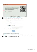
Страница 51: ...nter error code validation code and service tag Part serial number is optional NOTE For error code use only the last 3 or 4 digits of the code user can enter 0142 or 142 instead of 2000 0142 4 Click on Submit once all the necessary information is entered Troubleshooting 51 ...

Страница 52: ...Results Valid Error Code Example After entering the correct information the online tools will direct the user to the above screen which contains information on 52 Troubleshooting ...

Страница 53: ...tag Invalid Error Code Example QR APP Validation Tool About this task Besides using the online tool customers can also validate the error code by scanning the QR code with a QR APP on a smartphone Steps 1 User to obtain the QR code from SupportAssist On board Diagnostics error screen 2 User can use any QR code scanner application through the smartphone to scan the QR code Troubleshooting 53 ...

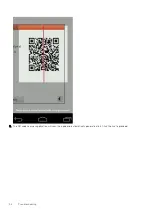
Страница 54: ...3 The QR code scanner application will scan the code and automatically generate a link Click the link to proceed 54 Troubleshooting ...

Страница 55: ...l Support website which contains information on Confirmation of the error code and result outcome Suggested Part Replacement If customer is still covered under Dell Warranty Case reference number if there is an open case under the service tag Troubleshooting 55 ...

Страница 56: ...nteractive mode Repeat tests Display or save test results Run thorough tests to introduce additional test options to provide extra information about the failed device s View status messages that inform you if tests are completed successfully View error messages that inform you of problems encountered during testing NOTE The SupportAssist window displays listing all devices detected in the computer...

Страница 57: ... the battery has less than 5 percent charge Off Power adapter is connected and the battery is fully charged Computer is running on battery and the battery has more than 5 percent charge Computer is in sleep state hibernation or turned off The power and battery status light blinks amber along with beep codes indicating failures For example the power and battery status light blinks amber two times f...

Страница 58: ...t found Flash latest BIOS version If problem persists replace the system board 3 4 Recovery image found but invalid Flash latest BIOS version If problem persists replace the system board 3 5 Power rail failure Replace system board 3 6 System BIOS Flash incomplete Replace system board 3 7 Management Engine ME error Replace system board Camera status light Indicates whether the camera is in use Soli...

Страница 59: ...ows operating system on your Dell PC For more information see Dell Windows Backup Media and Recovery Options WiFi power cycle About this task If your computer is unable to access the internet due to WiFi connectivity issues a WiFi power cycle procedure may be performed The following procedure provides the instructions on how to conduct a WiFi power cycle NOTE Some ISPs Internet Service Providers p...

Страница 60: ...5 Press and hold the power button for 20 seconds to drain the flea power 6 Install the battery 7 Install the base cover 8 Connect the power adapter to your computer 9 Turn on your computer NOTE For more information about performing a hard reset see the knowledge base article 000130881 at www dell com support 60 Troubleshooting ...

Страница 61: ...ck Search to retrieve the related articles Learn and know the following information about your product Product specifications Operating system Setting up and using your product Data backup Troubleshooting and diagnostics Factory and system restore BIOS information See Me and My Dell at www dell com support manuals To locate the Me and My Dell relevant to your product identify your product through ...

Отзывы: