background image

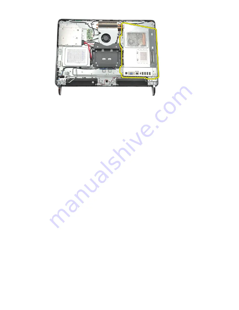
Installing The System Board Shield

1.

Place the system board shield on the chassis.

2.

Tighten the screws to secure the system board shield.

3.

Install the 

I/O panel

.

4.

Install the 

rear I/O cover

.

5.

Install the 

rear stand

.

6.

Install the 

rear cover

.

7.

Follow the procedures in 

After Working Inside Your Computer

.

36

Содержание Vostro 360

Страница 1: ...Dell Vostro 360 Owner s Manual Regulatory Model W03C Regulatory Type W03C001 ...

Страница 2: ...ks of Intel Corporation in the U S and other countries AMD is a registered trademark and AMD Opteron AMD Phenom AMD Sempron AMD Athlon ATI Radeon and ATI FirePro are trademarks of Advanced Micro Devices Inc Microsoft Windows MS DOS Windows Vista the Windows Vista start button and Office Outlook are either trademarks or registered trademarks of Microsoft Corporation in the United States and or othe...

Страница 3: ...Installing The Rear Cover 12 3 Removing The Rear Stand 13 Installing The Rear Stand 14 4 Removing The Front Feet 15 Installing The Front Feet 16 5 Removing The Rear Stand Cover 17 Installing The Rear Stand Cover 18 6 Removing The Rear I O Cover 19 Installing The Rear Input Output I O Cover 20 7 Removing The Optical Drive 21 Installing The Optical Drive 23 8 Removing The Memory Module 25 Installing...

Страница 4: ...Installing The Speakers 40 14 Removing The Middle Frame 41 Installing The Middle Frame 42 15 Removing The Touch Control Board 43 Installing The Touch Control Board 44 16 Removing The Power Switch Assembly 45 Installing The Power Switch Assembly 46 17 Removing The Coin Cell Battery 47 Installing The Coin Cell Battery 48 18 Removing The Heatsink Fan 49 Installing The Heatsink Fan 50 19 Removing The ...

Страница 5: ...alling The Speaker Cover 70 26 Removing The Front Bezel 71 Installing The Front Bezel 72 27 Removing The Low Voltage Differential Signaling LVDS Cable 73 Installing The Low Voltage Differential Signaling LVDS Cable 74 28 Removing The Display Panel 77 Installing The Display Panel 78 29 Removing The Webcamera 79 Installing The Webcamera 80 30 Removing The Antenna 81 Installing The Antenna 83 31 Syst...

Страница 6: ...System Setup Options 87 32 Diagnostic Error Messages 91 Diagnostic Beep Codes 92 Diagnostic Power LED Codes 93 33 Technical Specifications 95 34 Contacting Dell 101 Contacting Dell 101 ...

Страница 7: ...cumentation or as directed by the online or telephone service and support team Damage due to servicing that is not authorized by Dell is not covered by your warranty Read and follow the safety instructions that came with the product CAUTION To avoid electrostatic discharge ground yourself by using a wrist grounding strap or by periodically touching an unpainted metal surface such as a connector on...

Страница 8: ...trical outlets 5 Press and hold the power button while the computer is unplugged to ground the system board 6 Remove the cover CAUTION Before touching anything inside your computer ground yourself by touching an unpainted metal surface such as the metal at the back of the computer While you work periodically touch an unpainted metal surface to dissipate static electricity which could harm internal...

Страница 9: ...g system press and hold the power button for about 4 seconds to turn them off After Working Inside Your Computer After you complete any replacement procedure ensure you connect any external devices cards and cables before turning on your computer 1 Replace the cover CAUTION To connect a network cable first plug the cable into the network device and then plug it into the computer 2 Connect any tele...

Страница 10: ...10 ...

Страница 11: ...ng The Rear Cover 1 Follow the procedures in Before Working Inside Your Computer 2 Remove the screws that secure the rear cover 3 Pry the cover away from the computer 4 Lift the cover away from the computer 11 ...

Страница 12: ...er 1 Place the rear cover on the chassis 2 Press down on the rear cover until it clicks into place 3 Replace the screws to secure the rear cover to the computer 4 Follow the procedures in After Working Inside Your Computer 12 ...

Страница 13: ... Follow the procedures in Before Working Inside Your Computer 2 Remove the rear cover 3 Remove the screws that secure the rear stand to the computer 4 Pull the rear stand in an upwards direction and remove it from the chassis 13 ...

Страница 14: ...d 1 Align the rear stand into the chassis and ensure it clicks into place 2 Tighten the screws to secure the rear stand to the computer 3 Install the rear cover 4 Follow the procedures in After Working Inside Your Computer 14 ...

Страница 15: ...t 1 Follow the procedures in Before Working Inside Your Computer 2 Remove the rear cover 3 Remove the screws that secure the left front foot 4 Remove the left front foot 5 Remove the screws that secure the right front foot 15 ...

Страница 16: ...alling The Front Feet 1 Align the front feet to the bottom left and right of chassis 2 Tighten the screws to secure the left and right front feet 3 Install the rear cover 4 Follow the procedures in After Working Inside Your Computer 16 ...

Страница 17: ...e procedures in Before Working Inside Your Computer 2 Remove the rear cover 3 Remove the rear stand 4 Remove the screws that secure the top and the inside of the rear stand cover 5 Lift up the rear stand cover and remove it from the computer 17 ...

Страница 18: ...lign the rear stand cover on the chassis 2 Tighten the screws to secure the outside and the inside of the rear stand cover 3 Install the rear stand 4 Install the rear cover 5 Follow the procedures in After Working Inside Your Computer 18 ...

Страница 19: ...r 1 Follow the procedures in Before Working Inside Your Computer 2 Remove the rear cover 3 Remove the rear stand 4 Remove the screws that secure the rear I O cover 5 Pry the rear I O cover loose from the chassis and lift it up 19 ...

Страница 20: ... O Cover 1 Align and secure the rear I O cover on the chassis 2 Tighten the screws to secure the rear I O cover in place 3 Install the rear stand 4 Install the rear cover 5 Follow the procedures in After Working Inside Your Computer 20 ...

Страница 21: ...he procedures in Before Working Inside Your Computer 2 Remove the rear cover 3 Disconnect the SATA cable from the optical drive 4 Remove the screw that secures the optical drive to the chassis 5 Slide the optical drive out of the computer 21 ...

Страница 22: ...6 Remove the screws that secure the optical drive holder 7 Remove the holder from the optical drive module 22 ...

Страница 23: ... the screw to secure the optical drive 2 Slide the optical drive back into the computer 3 Tighten the screw to secure the optical drive to the chassis 4 Connect the SATA cable to the optical drive 5 Install the rear cover 6 Follow the procedures in After Working Inside Your Computer 23 ...

Страница 24: ...24 ...

Страница 25: ...in Before Working Inside Your Computer 2 Remove the rear cover 3 Pry the memory cover and lift it up from the computer 4 Pry the retention clips away from the memory module until it pops up 5 Remove the memory module from its connector on the computer 25 ...

Страница 26: ...6 Pry the retention clips away from the second memory module until it pops up 7 Remove the second memory module from its connector on the computer 26 ...

Страница 27: ...emory Module 1 Insert the memory module into the memory socket 2 Press the retention clips to secure the memory module in place 3 Install the rear cover 4 Follow the procedures in After Working Inside Your Computer 27 ...

Страница 28: ...28 ...

Страница 29: ...ng Inside Your Computer 2 Remove the rear cover 3 Remove the rear I O cover 4 Remove the rear stand 5 Remove the screw that secures the hard drive bracket to the chassis 6 Slide the hard drive bracket towards the outside of the computer to release the tabs from the chassis 29 ...

Страница 30: ...onnect the hard drive cable from the hard drive 8 Lift the hard drive bracket out of the chassis Remove the screws that secure the hard drive cage to the hard drive 9 Slide the hard drive out from the cage 30 ...

Страница 31: ...drive to the hard drive cage 3 Slide and push the hard drive bracket into the chassis to secure it 4 Tighten the screw to secure the hard drive bracket to the chassis 5 Install the rear stand 6 Install the rear I O cover 7 Install the rear cover 8 Follow the procedures in After Working Inside Your Computer 31 ...

Страница 32: ...32 ...

Страница 33: ...oard shield 6 Remove the I O panel away from the chassis Installing The Input Output Panel 1 Place the system board shield on the chassis 2 Tighten the screws to secure the system board shield 3 Install the I O panel securely on the system board shield 4 Install the rear I O cover 5 Install the rear stand 6 Install the rear cover 7 Follow the procedures in After Working Inside Your Computer 33 ...

Страница 34: ...34 ...

Страница 35: ...fore Working Inside Your Computer 2 Remove the rear cover 3 Remove the rear stand 4 Remove the rear I O cover 5 Remove the I O panel 6 Remove the screws that secure the system board shield 7 Tilt the system board shield at an angle and remove it from the computer 35 ...

Страница 36: ...em board shield on the chassis 2 Tighten the screws to secure the system board shield 3 Install the I O panel 4 Install the rear I O cover 5 Install the rear stand 6 Install the rear cover 7 Follow the procedures in After Working Inside Your Computer 36 ...

Страница 37: ...ing Inside Your Computer 2 Remove the rear cover 3 Remove the rear stand 4 Remove the rear I O cover 5 Remove the system board shield 6 Disconnect the antenna cables from the WLAN card 7 Remove the screw that secures the WLAN card and remove it from the computer 37 ...

Страница 38: ...to secure the WLAN card in place 3 Connect the antenna cables according to the color code on the WLAN card 4 Install the system board shield 5 Install the rear I O cover 6 Install the rear stand 7 Install the rear cover 8 Follow the procedures in After Working Inside Your Computer 38 ...

Страница 39: ...ore Working Inside Your Computer 2 Remove the rear cover 3 Remove the rear stand 4 Remove the rear I O cover 5 Remove the system board shield 6 Disconnect the speaker cable from the system board 7 Remove the screws that secure the right and left speakers 39 ...

Страница 40: ... chassis 2 Tighten the screws to secure both the speakers in place 3 Connect the speaker cable to the system board 4 Install the system board shield 5 Install the rear I O cover 6 Install the rear stand 7 Install the rear cover 8 Follow the procedures in After Working Inside Your Computer 40 ...

Страница 41: ...efore Working Inside Your Computer 2 Remove the rear cover 3 Remove the rear stand 4 Remove the rear I O cover 5 Remove the front foot 6 Remove the optical drive 7 Remove the screws that secure the middle frame 8 Pry the middle frame loose from the chassis 41 ...

Страница 42: ...ssis 2 Secure the clips until all of them snap on to the chassis 3 Tighten the screws to secure the middle frame 4 Install the optical drive 5 Install the front feet 6 Install the rear I O cover 7 Install the rear stand 8 Install the rear cover 9 Follow the procedures in After Working Inside Your Computer 42 ...

Страница 43: ... Before Working Inside Your Computer 2 Remove the rear cover 3 Disconnect the connector cables from the touch control board NOTE The touch control board and the cable are part of the display Panel assembly 4 Remove the screws that secure the touch control board 43 ...

Страница 44: ...ntrol Board 1 Place the touch control board on the chassis 2 Tighten the screws to secure the touch control board 3 Connect the connector cables into place on the touch control board 4 Install the rear cover 5 Follow the procedures in After Working Inside Your Computer 44 ...

Страница 45: ...dures in Before Working Inside Your Computer 2 Remove the rear cover 3 Remove the rear stand 4 Remove the rear I O cover 5 Remove the screw that secures the power switch assembly to the chassis 6 Disconnect the power switch assembly from the system board 45 ...

Страница 46: ...ssembly on the chassis 2 Connect the power switch assembly cable to the system board and thread the cables into the chassis clips 3 Tighten the screw that secures the power switch assembly to the chassis 4 Install the rear I O cover 5 Install the rear stand 6 Install the rear cover 7 Follow the procedures in After Working Inside Your Computer 46 ...

Страница 47: ...Before Working Inside Your Computer 2 Remove the rear cover 3 Remove the rear stand 4 Remove the rear I O cover 5 Remove the system board shield 6 Pry the tabs that secure the coin cell battery to the system board 7 Remove the coin cell battery from its socket 47 ...

Страница 48: ...ttery 1 Insert the coin cell battery into the slot 2 Install the system board shield 3 Install the rear I O cover 4 Install the rear stand 5 Install the rear cover 6 Follow the procedures in After Working Inside Your Computer 48 ...

Страница 49: ...efore Working Inside Your Computer 2 Remove the rear cover 3 Remove the rear stand 4 Remove the rear I O cover 5 Remove the system board shield 6 Remove the screws that secure the fan to the chassis 7 Disconnect the heatsink fan cable from the system board 49 ...

Страница 50: ...hassis 2 Tighten the screws to secure the heatsink fan to the chassis 3 Connect the heatsink fan connector to its socket on the system board 4 Install the system board shield 5 Install the rear I O cover 6 Install the rear stand 7 Install the rear cover 8 Follow the procedures in After Working Inside Your Computer 50 ...

Страница 51: ...side Your Computer 2 Remove the rear cover 3 Remove the rear stand 4 Remove the rear I O cover 5 Remove the rear stand cover 6 Remove the system board shield 7 Disconnect the power cable from the system board 8 Remove the white cable from the connector on the converter board 51 ...

Страница 52: ...9 Remove the screws that secure the converter board 10 Lift up and remove the converter board from the computer 52 ...

Страница 53: ...ard 2 Insert the white cable into the connector on the converter board 3 Install the system board shield 4 Install the rear stand cover 5 Install the rear I O cover 6 Install the rear stand 7 Install the rear cover 8 Follow the procedures in After Working Inside Your Computer 53 ...

Страница 54: ...54 ...

Страница 55: ...Working Inside Your Computer 2 Remove the rear cover 3 Remove the rear stand 4 Remove the rear I O cover 5 Remove the rear stand cover 6 Remove the system board shield 7 Disconnect the CPU fan cable 8 Remove the screws that secure the CPU fan to the chassis 55 ...

Страница 56: ...re the CPU fan to the chassis 2 Secure the tape sealing the CPU fan to the heatsink 3 Connect the CPU fan connector to the system board 4 Install the system board shield 5 Install the rear stand cover 6 Install the rear I O cover 7 Install the rear stand 8 Install the rear cover 9 Follow the procedures in After Working Inside Your Computer 56 ...

Страница 57: ...ver 3 Remove the rear stand 4 Remove the rear I O cover 5 Remove the rear stand cover 6 Remove the system board shield 7 Remove the CPU fan 8 Remove the screw that secures the heatsink to the chassis and remove the screws that secure the heatsink to the system board 9 Remove the heatsink from the computer 57 ...

Страница 58: ... to the system board and also tighten the screw that secures the heatsink to the chassis 3 Install the CPU fan 4 Install the system board shield 5 Install the rear stand cover 6 Install the rear I O cover 7 Install the rear stand 8 Install the rear cover 9 Follow the procedures in After Working Inside Your Computer 58 ...

Страница 59: ... the rear I O cover 5 Remove the rear stand cover 6 Remove the system board shield 7 Remove the CPU fan 8 Remove the CPU heatsink 9 Press the release lever down and then move it outward to release it from the retention hook that secures it 10 Lift the processor cover and remove the processor from the socket Place it in an antistatic packaging 59 ...

Страница 60: ...ess the release lever down and then move it inward to secure it with the retention hook 4 Install the CPU heatsink 5 Install the CPU fan 6 Install the system board shield 7 Install the rear stand cover 8 Install the rear I O cover 9 Install the rear stand 10 Install the rear cover 11 Follow the procedures in After Working Inside Your Computer 60 ...

Страница 61: ...ar I O cover 5 Remove the rear stand cover 6 Remove the system board shield 7 Remove the CPU fan 8 Remove the CPU heatsink 9 Remove the memory module 10 Remove the WLAN card 11 Remove the coin cell battery 12 Remove the processor 13 Disconnect all the cables connected to the system board 14 Remove the screws that secure the system board to the chassis 61 ...

Страница 62: ... chassis and place it on the chassis 2 Install the screws that secure the system board to the chassis 3 Connect the cables to the system board 4 Install the processor 5 Install the coin cell battery 6 Install the WLAN card 7 Install the memory module 8 Install the CPU heatsink 9 Install the CPU fan 10 Install the system board shield 62 ...

Страница 63: ...11 Install the rear stand cover 12 Install the rear I O cover 13 Install the rear stand 14 Install the rear cover 15 Follow the procedures in After Working Inside Your Computer 63 ...

Страница 64: ...64 ...

Страница 65: ...he hard drive cage and the hard drive 8 Remove the optical drive 9 Remove the system board shield 10 Remove the CPU fan 11 Remove the CPU heatsink 12 Remove the system board 13 Remove the speakers 14 Remove the converter board 15 Remove the power switch assembly 16 Remove the touch control board 17 Remove the black screws that secure the tempan to the chassis 18 Remove the silver screws that secur...

Страница 66: ...19 Unthread the cables from the chassis clips 20 Slide the tempan out from the chassis and remove it 66 ...

Страница 67: ...the power switch assembly 6 Install the converter board 7 Install the speakers 8 Install the system board 9 Install the CPU heatsink 10 Install the CPU fan 11 Install the system board shield 12 Install the optical drive 13 Install the hard drive cage and hard drive 14 Install the middle frame 15 Install the rear I O cover 16 Install the rear stand cover 17 Install the rear stand 18 Install the rea...

Страница 68: ...68 ...

Страница 69: ...ver 3 Remove the rear stand 4 Remove the rear stand cover 5 Remove the rear I O cover 6 Remove the front foot 7 Remove the middle frame 8 Remove the optical drive 9 Remove the speakers 10 Remove the screws that secure the speaker cover to the chassis 11 Pry the speaker cover loose from the chassis and remove it 69 ...

Страница 70: ... to secure the speaker cover to the chassis 3 Install the speakers 4 Install the optical drive 5 Install the middle frame 6 Install the front feet 7 Install the rear I O cover 8 Install the rear stand 9 Install the rear cover 10 Follow the procedures in After Working Inside Your Computer 70 ...

Страница 71: ... the middle frame 7 Remove the system board shield 8 Remove the hard drive cage and the hard drive 9 Remove the optical drive 10 Remove the CPU fan 11 Remove the CPU heatsink 12 Remove the system board 13 Remove the tempan 14 Remove the speakers 15 Remove the speaker cover 16 Remove the screws marked with an arrow that secure the front bezel to the display panel 17 Lift the chassis off the front b...

Страница 72: ... 6 Install the tempan 7 Install the system board 8 Install the CPU heatsink 9 Install the CPU fan 10 Install the optical drive 11 Install the hard drive cage and hard drive 12 Install the system board shield 13 Install the middle frame 14 Install the rear stand cover 15 Install the rear I O cover 16 Install the rear stand 17 Install the rear cover 18 Follow the procedures in After Working Inside Y...

Страница 73: ... the rear stand cover 6 Remove the middle frame 7 Remove the system board shield 8 Remove the hard drive cage and the hard drive 9 Remove the optical drive 10 Remove the CPU fan 11 Remove the CPU heatsink 12 Remove the system board 13 Remove the tempan 14 Pry up the front of the display panel on a soft pad so that the touch cameras are off the table 15 Peel back the plastic tape that secures the c...

Страница 74: ... LVDS Cable 1 Connect the LVDS cable to its connector 2 Secure the plastic tape that connects the LVDS cable to the chassis 3 Install the tempan 4 Install the system board 5 Install the CPU heatsink 6 Install the CPU fan 7 Install the optical drive 8 Install the hard drive cage and hard drive 9 Install the system board shield 74 ...

Страница 75: ...Install the middle frame 11 Install the rear stand cover 12 Install the rear I O cover 13 Install the rear stand 14 Install the rear cover 15 Follow the procedures in After Working Inside Your Computer 75 ...

Страница 76: ...76 ...

Страница 77: ... I O cover 5 Remove the rear stand cover 6 Remove the middle frame 7 Remove the system board shield 8 Remove the hard drive cage and the hard drive 9 Remove the optical drive 10 Remove the CPU fan 11 Remove the CPU heatsink 12 Remove the system board 13 Remove the speakers 14 Remove the speaker cover 15 Remove the front bezel 16 Remove the LVDS cable 17 Remove the tempan 18 Remove the screws from ...

Страница 78: ...panel 3 Install the tempan 4 Install the LVDS cable 5 Install the front bezel 6 Install the speaker cover 7 Install the speakers 8 Install the system board 9 Install the CPU heatsink 10 Install the CPU fan 11 Install the optical drive 12 Install the hard drive cage and hard drive 13 Install the system board shield 14 Install the middle frame 15 Install the rear stand cover 16 Install the rear I O ...

Страница 79: ...emove the middle frame 7 Remove the system board shield 8 Remove the hard drive cage and the hard drive 9 Remove the optical drive 10 Remove the CPU fan 11 Remove the CPU heatsink 12 Remove the system board 13 Remove the speakers 14 Remove the speaker cover 15 Remove the front bezel 16 Remove the tempan 17 Remove the screws that secure the webcamera 18 Remove the webcamera along with its cable 79 ...

Страница 80: ...nstall the speaker cover 7 Install the speakers 8 Install the system board 9 Install the CPU heatsink 10 Install the CPU fan 11 Install the optical drive 12 Install the hard drive cage and hard drive 13 Install the system board shield 14 Install the middle frame 15 Install the rear stand cover 16 Install the rear I O cover 17 Install the rear stand 18 Install the rear cover 19 Follow the procedure...

Страница 81: ... 6 Remove the middle frame 7 Remove the system board shield 8 Remove the hard drive cage and the hard drive 9 Remove the optical drive 10 Remove the CPU fan 11 Remove the CPU heatsink 12 Remove the system board 13 Remove the speakers 14 Remove the speaker cover 15 Remove the tempan 16 Remove the cables from the chassis clips 17 Remove the aluminium conducting tape that secure the antennae 81 ...

Страница 82: ...18 Remove the screws that secure each antenna 19 Lift up the antennae with its cables 82 ...

Страница 83: ...tall the speaker cover 7 Install the speakers 8 Install the system board 9 Install the CPU heatsink 10 Install the CPU fan 11 Install the optical drive 12 Install the hard drive cage and hard drive 13 Install the system board shield 14 Install the middle frame 15 Install the rear stand cover 16 Install the rear I O cover 17 Install the rear stand 18 Install the rear cover 19 Follow the procedures ...

Страница 84: ...84 ...

Страница 85: ...uter 2 When the blue DELL logo is displayed you must watch for the F2 prompt to appear 3 Once the F2 prompt appears press F2 immediately NOTE The F2 prompt indicates that the keyboard has initialized This prompt can appear very quickly so you must watch for it to display and then press F2 If you press F2 before you are prompted this keystroke will be lost 4 If you wait too long and the operating s...

Страница 86: ... Press ESC to return to the Options List NOTE Not all settings listed in the Options Field are changeable Help Appears on the right side of the System Setup window and contains help information about the option selected in Options List Key Functions Appears below the Options Field and lists keys and their functions within the active system setup field Use the following keys to navigate through the...

Страница 87: ... Tag Displays the service tag of your computer Asset Tag Displays the asset tag of your computer Processor Information Processor Type Displays the type of processor L2 Cache Size Displays the processor L2 cache size L3 Cache Size Displays the processor L3 cache size Memory Information Memory Installed Displays the total computer memory Memory Speed Displays the memory speed Memory Technology Displ...

Страница 88: ...logy Enable or disable the Intel Virtualization feature Default Enabled Intel SpeedStep Enable or disable the Intel SpeedStep feature Default Enabled System Configuration Onboard Audio Controller Enable or disable the onboard audio controller Default Enabled Onboard LAN Controller Enable or disable the onboard LAN controller Default Enabled Onboard LAN Boot ROM Enable or disable the onboard LAN bo...

Страница 89: ...or Report Enable or disable the Keyboard Error Report to be displayed during POST Default Enabled Security The Security tab displays the security status and allows you to manage the security features of the computer Admin Password Status Specifies whether an admin password has been assigned Set Admin Password Allows you to set an admin password HDD Protection Allows you to set a Hard Drive passwor...

Страница 90: ...90 ...

Страница 91: ...outine three consecutive times for the same error System fan failure Possible fan failure CPU fan failure CPU fan has failed Hard disk drive failure Possible hard disk drive failure during POST Hard disk drive read failure Possible hard disk drive failure during HDD boot test Keyboard failure Keyboard failure or loose cable If reseating the cable does not solve the problem replace the keyboard RTC...

Страница 92: ... range Dell recommends that you back up your data regularly A parameter out of range may or may not indicate a potential hard drive problem S M A R T error possible hard disk drive failure Diagnostic Beep Codes No POST with three beeps is accompanied by a blinking amber power LED All other beep codes will be accompanied by a solid white power LED Refer to the table below for each scenario Beep Des...

Страница 93: ...ower State OFF Power is off or the system is in an S4 hibernate or S5 Powered Off power state LED is blank Solid White The computer is in power on state Solid Amber The system board cannot start initialization There may be an issue with the system board memory processor or the power supply Blinking Amber The system board cannot start initialization or in an S3 Sleep state power state There is a po...

Страница 94: ...94 ...

Страница 95: ...ion to view information about your computer System Information System Chipset Intel H61 Express Chipset DMA Channels up to 8 MB depending on the processor type Interrupt Levels ACPI IRQ 0 31 BIOS Chip NVRAM 32 MB Processor Type Intel Core i3 i5 i7 series Intel Pentium Dual Core Total Cache up to 8 MB depending on the processor type Memory Speed DDR3 with 1333 MHz Connector two SO DIMM slots Capaci...

Страница 96: ...ches HD WLED Dimensions Height 312 50 mm 12 30 inches Width 533 70 mm 21 01 inches Diagonal 584 20 mm 23 inches Maximum Resolution 1920 x 1080 Operating angle CR 10 Horizontal viewing angle 170 Vertical viewing angle 160 Pixel pitch 0 27 mm x 0 27 mm Audio Integrated HD Audio with SRS Camera Camera and Microphone HD Webcam with integrated digital microphone Communication Network adapter 10 100 100...

Страница 97: ...h drive bay Internally accessible one 3 5 inch SATA drive bay External Connectors Audio Left Panel two connectors for headphone and microphone Back panel one line out connector Network one RJ 45 connector USB Left panel two USB 2 0 connectors Back panel four USB 2 0 connectors Video one VGA connector Memory card reader one 8 in 1 memory card reader System Board Connectors Serial ATA two Memory two...

Страница 98: ...or during the Power on self test POST Drive activity light White light Blinking white light indicates that the computer is reading data from or writing data to the hard drive Network connectivity light Green light A good connection exists between the network and the computer Off no light The computer is not detecting a physical connection to the network AC Adapter Input voltage 100 VAC to 240 VAC ...

Страница 99: ...inches Width 568 00 mm 22 36 inches Depth Touchscreen 79 00 mm 3 11 inches Non touchscreen 75 50 mm 2 97 inches Weight minimum Touchscreen 9 35 kg 20 61 lb Non touchscreen 8 65 kg 19 07 lb Environmental Temperature Operating 10 C to 35 C 50 F to 95 F Storage 40 C to 65 C 40 F to 149 F Relative humidity 20 to 80 noncondensing Maximum vibration Operating 0 26 Grms Non Operating 2 20 Grms Maximum sho...

Страница 100: ...0 G for 22 ms with a change in velocity of 240 inches s 609 cm s Altitude Operating 15 20 m to 3048 m 50 ft to 10 000 ft Storage 15 20 m to 10 668 m 50 ft to 35 000 ft Airborne contaminant level G1 as defined by ISA S71 04 1985 100 ...

Страница 101: ... support and service options Availability varies by country and product and some services may not be available in your area To contact Dell for sales technical support or customer service issues 1 Visit support dell com 2 Select your support category 3 If you are not a U S customer select your country code at the bottom of the page or select All to see more choices 4 Select the appropriate service...

Отзывы: