background image

Contents

Notes, Cautions, and Warnings.............................................................................................. 0

1 Working on Your Computer.......................................................................................................5

Before Working Inside Your Computer

.....................................................................................................................5

Turning Off Your Computer

.......................................................................................................................................6

After Working Inside Your Computer

........................................................................................................................6

2 Removing and Installing Components.....................................................................................9

Recommended Tools

................................................................................................................................................9

Removing the Secure Digital (SD) Card

....................................................................................................................9

Installing the Secure Digital (SD) Card

.....................................................................................................................9

Removing the Battery

...............................................................................................................................................9

Installing the Battery

..............................................................................................................................................10

Removing the Access Panel

...................................................................................................................................10

Installing the Access Panel

....................................................................................................................................11

Removing the Memory Module

..............................................................................................................................11

Installing the Memory Module

................................................................................................................................12

Removing the Hard-Drive Assembly

.......................................................................................................................12

Installing the Hard-Drive Assembly

........................................................................................................................13

Removing the Optical-Drive Assembly

...................................................................................................................14

Installing the Optical-Drive Assembly

....................................................................................................................15

Removing the Keyboard

..........................................................................................................................................15

Installing the Keyboard

...........................................................................................................................................17

Removing the Wireless Mini-Card

..........................................................................................................................17

Installing the Wireless Mini-Card

...........................................................................................................................17

Removing the Palmrest

...........................................................................................................................................17

Installing the Palmrest

............................................................................................................................................20

Removing the Input/Output (I/O) Board

..................................................................................................................20

Installing the Input/Output (I/O) Board

...................................................................................................................21

Removing the Coin-Cell Battery

..............................................................................................................................21

Installing the Coin-Cell Battery

...............................................................................................................................22

Removing the System Board

...................................................................................................................................22

Installing the System Board

....................................................................................................................................24

Removing the Heatsink

...........................................................................................................................................25

Installing the Heatsink

............................................................................................................................................25

Removing the Speakers

..........................................................................................................................................26

Содержание Vostro 2421

Страница 1: ...Dell Vostro 2421 Owner s Manual Regulatory Model P37G Regulatory Type P37G001 ...

Страница 2: ...Installing the Memory Module 12 Removing the Hard Drive Assembly 12 Installing the Hard Drive Assembly 13 Removing the Optical Drive Assembly 14 Installing the Optical Drive Assembly 15 Removing the Keyboard 15 Installing the Keyboard 17 Removing the Wireless Mini Card 17 Installing the Wireless Mini Card 17 Removing the Palmrest 17 Installing the Palmrest 20 Removing the Input Output I O Board 20...

Страница 3: ...ges 33 Removing the Camera Module 34 Installing the Camera Module 35 3 System Setup 37 Boot Sequence 37 Navigation Keys 37 System Setup Options 38 Updating the BIOS 41 System and Setup Password 41 Assigning a System Password and Setup Password 42 Deleting or Changing an Existing System and or Setup Password 42 4 Troubleshooting 45 Enhanced Pre Boot System Assessment ePSA Diagnostics 45 Diagnostics...

Страница 4: ...4 ...

Страница 5: ...s and cards with care Do not touch the components or contacts on a card Hold a card by its edges or by its metal mounting bracket Hold a component such as a processor by its edges not by its pins CAUTION When you disconnect a cable pull on its connector or on its pull tab not on the cable itself Some cables have connectors with locking tabs if you are disconnecting this type of cable press in on t...

Страница 6: ...uch enabled device a Swipe in from the right edge of the screen opening the Charms menu and select Settings b Select the and then select Shut down Using a mouse a Point to upper right corner of the screen and click Settings b Click the and select Shut down In Windows 7 1 Click Start 2 Click Shut Down or 1 Click Start 2 Click the arrow in the lower right corner of the Start menu as shown below and ...

Страница 7: ...s an ExpressCard 2 Connect any telephone or network cables to your computer CAUTION To connect a network cable first plug the cable into the network device and then plug it into the computer 3 Replace the battery 4 Connect your computer and all attached devices to their electrical outlets 5 Turn on your computer 7 ...

Страница 8: ...8 ...

Страница 9: ...e Digital SD Card 1 Follow the procedures in Before Working Inside Your Computer 2 Press in on the SD memory card to release it from the computer Installing the Secure Digital SD Card 1 Push the memory card into the compartment until it clicks into place 2 Follow the procedures in After Working Inside Your Computer Removing the Battery 1 Follow the procedures in Before Working Inside Your Computer...

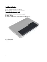
Страница 10: ...ce 2 Follow the procedures in After Working Inside Your Computer Removing the Access Panel 1 Follow the procedures in Before Working Inside Your Computer 2 Remove the battery 3 Loosen the screw that secures the access panel and remove it from the computer 4 Lift the access panel 10 ...

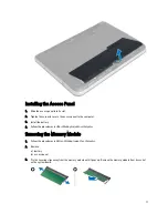
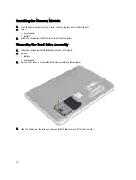
Страница 11: ...tall the battery 4 Follow the procedures in After Working Inside Your Computer Removing the Memory Module 1 Follow the procedures in Before Working Inside Your Computer 2 Remove a battery b access panel 3 Pry the securing clips away from the memory module until it pops up Remove the memory module from its socket on the system board 11 ...

Страница 12: ...llow the procedures in After Working Inside Your Computer Removing the Hard Drive Assembly 1 Follow the procedures in Before Working Inside Your Computer 2 Remove a battery b access panel 3 Remove the screws that secure the hard drive assembly to the computer 4 Slide the hard drive in the direction shown and lift the tab to remove it from the computer 12 ...

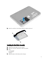
Страница 13: ...it Installing the Hard Drive Assembly 1 Slide the hard drive assembly in its slot in the computer 2 Tighten the screw to secure the hard drive assembly to the computer 3 Install a memory module b access panel c battery 4 Follow the procedures in After Working Inside Your Computer 13 ...

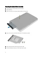
Страница 14: ...y 3 Remove the screw that secures the optical drive and slide it out of the drive bay 4 Remove the screws that secure the optical drive bracket to the optical drive assembly 5 Remove the optical drive bracket from the optical drive assembly 6 Pry the optical drive bezel and remove it from the optical drive assembly 14 ...

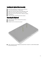
Страница 15: ...the drive bay in the computer 5 Tighten the screw to secure the optical drive assembly to the computer 6 Install the battery 7 Follow the procedures in After Working Inside Your Computer Removing the Keyboard 1 Follow the procedures in Before Working Inside Your Computer 2 Remove the battery 3 Remove the screws from the back of the computer 4 Flip the computer and release the keyboard by pressing ...

Страница 16: ...5 Disconnect the keyboard connector from the system board and lift it up to remove it from the computer 16 ...

Страница 17: ...ct the antennae from the card remove the screw and remove the wireless mini card from its slot on the system board Installing the Wireless Mini Card 1 Connect the antenna cables to their respective connectors marked on the wireless mini card 2 Insert the wireless mini card into its connector at a 45 degree angle into its slot 3 Press down the wireless mini card and tighten the screw to secure the ...

Страница 18: ...c access panel d keyboard 3 Remove the screws that secure the palmrest to the computer 4 Flip the computer and remove the screws that secure the palmrest to the system board 18 ...

Страница 19: ...d power button cable from the system board 6 Flip the computer and push the hooks inside the battery bay before releasing the plamrest 7 Flip the computer and release the tabs on the sides to lift the palmrest from the computer 19 ...

Страница 20: ...ecure the palmrest to the computer 5 Install a keyboard b optical drive assembly c memory module d access panel e battery 6 Follow the procedures in After Working Inside Your Computer Removing the Input Output I O Board 1 Follow the procedures in Before Working Inside Your Computer 2 Remove a battery b access panel c keyboard d palmrest 3 Disconnect the I O cable from the system board 4 Remove the...

Страница 21: ...cable to the system board 4 Install a palmrest b keyboard c access panel d battery 5 Follow the procedures in After Working Inside Your Computer Removing the Coin Cell Battery 1 Follow the procedures in Before Working Inside Your Computer 2 Remove a battery b access panel c keyboard d palmrest e wireless mini card 3 Pry out the coin cell battery from the system board 21 ...

Страница 22: ...3 Follow the procedures in After Working Inside Your Computer Removing the System Board 1 Follow the procedures in Before Working Inside Your Computer 2 Remove a battery b access panel c memory module d hard drive assembly e SD card f optical drive assembly g keyboard h palmrest i coin cell battery 3 Peel the tape that secures the display cable to the system board 22 ...

Страница 23: ...4 Disconnect the following cables a display b DC In Port c speaker d I O board 23 ...

Страница 24: ...n the screw to secure the system board to the computer 3 Connect the following cables a display b DC In Port c speaker d I O board 4 Affix the tape to secure the display cable to the system board 5 Install a wireless mini card b palmrest c keyboard d optical drive assembly e hard drive assembly f memory module g access panel h battery 6 Follow the procedures in After Working Inside Your Computer 2...

Страница 25: ...board g palmrest h wireless mini card i system board 3 Flip the system board and place it on a flat surface 4 Disconnect fan cable remove the screws that secure the heatsink to the system board Lift the heatsink from the system board Installing the Heatsink 1 Align the heatsink in its place on the system board 2 Tighten the screws to secure the heatsink to the system board 3 Install 25 ...

Страница 26: ...ter Working Inside Your Computer Removing the Speakers 1 Follow the procedures in Before Working Inside Your Computer 2 Remove a battery b access panel c memory module d hard drive assembly e optical drive assembly f keyboard g plamrest h wireless mini card i system board 3 Un route the speaker cable from its routing channel and lift the speaker assembly from the computer 26 ...

Страница 27: ...el h access panel i battery 3 Follow the procedures in After Working Inside Your Computer Removing the Display Assembly 1 Follow the procedures in Before Working Inside Your Computer 2 Remove a battery b access panel c memory module d hard drive assembly e optical drive assembly f keyboard g palmrest h system board 3 Un route the display cable from its channels 4 Remove the screws that secure the ...

Страница 28: ...ace the display assembly on the computer 2 Route the display cable to its channels 3 Install a system board b palmrest c keyboard d optical drive assembly e hard drive assembly f memory module g access panel h battery 4 Follow the procedures in After Working Inside Your Computer 28 ...

Страница 29: ... Remove a battery b access panel c memory module d hard drive assembly e optical drive assembly f keyboard g palmrest h display assembly 3 Press the hinge cover on the side Lift and remove it from the computer 4 Pry the edges of the display bezel Remove the display bezel from the computer 29 ...

Страница 30: ...mbly b palmrest c keyboard d optical drive assembly e hard drive assembly f memory module g access panel h battery 4 Follow the procedures in After Working Inside Your Computer Removing the Display Panel 1 Follow the procedures in Before Working Inside Your Computer 2 Remove a battery b access panel c memory module d hard drive assembly e optical drive assembly f keyboard 30 ...

Страница 31: ...el 3 Remove the screws that secure the display panel to the computer Lift the display panel and flip it 4 Peel the tape that secures display cable and disconnect the cable from the connector Remove the display panel from the display assembly 31 ...

Страница 32: ...the display panel to the computer 5 Install a display bezel b display assembly c palmrest d keyboard e optical drive assembly f hard drive assembly g memory module h access panel i battery 6 Follow the procedures in After Working Inside Your Computer Removing the Display Hinges 1 Follow the procedures in Before Working Inside Your Computer 2 Remove a battery b access panel c memory module 32 ...

Страница 33: ... off the display panel Installing the Display Hinges 1 Place the display hinge in its place on the display panel 2 Tighten the screws to secure the display hinge to the display panel 3 Install a display bezel b display assembly c palmrest d keyboard e optical drive assembly f hard drive assembly g memory module h access panel i battery 4 Follow the procedures in After Working Inside Your Computer ...

Страница 34: ... Computer 2 Remove a battery b access panel c memory module d hard drive assembly e optical drive assembly f keyboard g palmrest h display assembly i display bezel 3 Disconnect the camera cable from the connector on the camera module and lift the camera off the display assembly 34 ...

Страница 35: ... module 2 Align the camera module in its position on the computer 3 Install a display bezel b display assembly c palmrest d keyboard e optical drive assembly f hard drive assembly g memory module h access panel i battery 4 Follow the instructions in After Working Inside Your Computer 35 ...

Страница 36: ...36 ...

Страница 37: ...e boot menu displays the devices that you can boot from including the diagnostic option The boot menu options are Removable Drive if available STXXXX Drive NOTE XXX denotes the SATA drive number Optical Drive Diagnostics NOTE Choosing Diagnostics will display the ePSA diagnostics screen The boot sequence screen also displays the option to access the System Setup screen Navigation Keys The followin...

Страница 38: ...h option Table 2 Main Options Option Description System Time Allows you to reset the time on the computer s internal clock System Date Allows you to reset the date on the computer s internal calendar BIOS Version Displays the BIOS revision Product Name Displays the product name and the model number Service Tag Displays the service tag of your computer Asset Tag Displays the asset tag of your compu...

Страница 39: ...Enabled Virtualization Enable or disable the Intel Virtualization feature Default Enabled Integrated NIC Enable or disable the power supply to the on board network card Default Enabled USB Emulation Enable or disable the USB emulation feature Default Enabled USB Wake Support Allows USB devices to wake up the computer from standby This feature is enabled only when the AC adapter is connected Defaul...

Страница 40: ...ty Options Option Description Admin Password This field displays if a admin password is set for this computer or not Default Cleared Not installed System Password This field displays if a system password is set for this computer or not Default Cleared Not installed Hdd Password State This field displays if a HDD password is set for this computer or not Default Cleared Password Change Allows you to...

Страница 41: ...l is available at the back of your computer a Enter the Service Tag or Express Service Code and click Submit b Click Submit and proceed to step 5 4 If you do not have your computer s service tag or express service code select one of the following a Automatically detect my Service Tag for me b Choose from My Products and Services List c Choose from a list of all Dell products 5 On the application a...

Страница 42: ...racters The password can contain the numbers 0 through 9 Only lower case letters are valid upper case letters are not allowed Only the following special characters are allowed space Re enter the system password when prompted 4 Type the system password that you entered earlier and click OK 5 Select Setup Password type your system password and press Enter or Tab A message prompts you to re type the ...

Страница 43: ...ter the new password when promoted If you delete the System and or Setup password confirm the deletion when promoted 5 Press Esc and a message prompts you to save the changes 6 Press Y to save the changes and exit from the System Setup The computer reboots 43 ...

Страница 44: ...44 ...

Страница 45: ...quire user interaction Always ensure that you are present at the computer terminal when the diagnostic tests are performed 1 Power on the computer 2 As the computer boots press the F12 key as the Dell logo appears 3 On the boot menu screen select the Diagnostics option The Enhanced Pre boot System Assessment window is displayed listing all devices detected in the computer The diagnostics starts ru...

Страница 46: ...ter may emit a series of beeps during start up if the display cannot show errors or problems These series of beeps called beep codes identify various problems The delay between each beep is 300 ms the delay between each set of beeps is 3 seconds and the beep sound lasts 300 ms After each beep and each set of beeps the BIOS should detect if the user presses the power button If so BIOS will jump out...

Страница 47: ... two times pause etc This pattern continues until the system is powered off Code Cause and Troubleshooting Steps 1 System board BIOS ROM failure System board failure covers BIOS corruption or ROM error 2 Memory No memory RAM detected 3 Chipset Error North and South Bridge Chipset DMA IMR Timer Error Time Of Day Clock test failure Gate A20 failure Super I O chip failure Keyboard controller test fai...

Страница 48: ...48 ...

Страница 49: ...el Celeron Dual Core ULV Intel Pentium Dual Core ULV Intel Core i3 ULV Intel Core i5 ULV L1 cache 32 KB L2 cache 256 KB L3 cache Up to 4 MB Table 11 Memory Feature Description Memory connector two internally accessible DDR3 DDR3L connectors Memory capacity 2 GB and 4 GB Memory type 1600 MHz dual channel DDR3 configuration Minimum memory 2 GB 4 GB 6 GB and 8 GB Maximum memory 8 GB Table 12 Audio Fe...

Страница 50: ... fps maximum Diagonal viewing angle 66 Table 15 Communication Feature Description Network adapter 10 100 Mbps Ethernet LAN on Motherboard LOM Wireless Wi fi 802 11 b g n bluetooth 4 0 Table 16 Ports and Connectors Feature Description Audio one headphone microphone combo port headset Video one 19 pin HDMI connector Network adapter one RJ45 port USB two USB 3 0 ports rear one with window debug one U...

Страница 51: ...gle 0 closed to 135 Refresh rate 60 Hz Minimum Viewing angles Horizontal 40 40 Vertical 10 30 Pixel pitch 0 2265 mm x 0 2265 mm Table 18 Keyboard Feature Description Number of keys US 102 Brazil 105 UK 103 and Japan 106 Table 19 Touchpad Feature Description Active Area 240 dpi X axis 56 00 mm 2 20 inches Y axis 100 00 mm 3 94 inches Table 20 Battery Feature Description Type 4 cell smart lithium io...

Страница 52: ...ion Type Vostro 2421 with integrated video card 65 W Vostro 2421 with discrete video card 90 W Input voltage 100 VAC to 240 VAC Input current maximum 1 50 A 1 60 A 1 70 A 2 50 A Input frequency 50 Hz 60 Hz Output power 65 W 90 W Output current 3 34 A 4 62 A Rated output voltage 19 50 VDC Temperature range Operating 0 C to 40 C 32 F to 104 F Non Operating 40 C to 70 C 40 F to 158 F Table 22 Physica...

Страница 53: ... C to 65 C 40 F to 149 F Relative humidity maximum Operating 10 to 90 non condensing Storage 10 to 95 non condensing Altitude maximum Operating 15 2 m to 3048 m 50 to 10 000 ft 0 to 35 C Non Operating 15 2 m to 10 668 m 50 ft to 35 000 ft Airborne contaminant level G1 as defined by ISA S71 04 1985 53 ...

Страница 54: ...54 ...
Страница 55: ...support and service options Availability varies by country and product and some services may not be available in your area To contact Dell for sales technical support or customer service issues 1 Visit www dell com support 2 Select your support category 3 Verify your country or region in the Choose a Country Region drop down menu at the top of page 4 Select the appropriate service or support link ...

Отзывы: