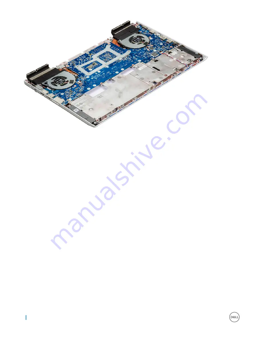
Installing the back cover
1
Press the edges of the back cover until it clicks into place.
2
Close the display assembly and turn over the system.
3
Replace the M2L3(4) and M2.5xL6 (19) screws to the back cover to the computer.
4
Connect the power, LED and Keyboard backlight cable, touchpad, keyboard cable and affix the white adhesive tape to the connector
to the computer.
5
Route the eDP cable through the routing and connect the cable to the computer.
6
Place the metal bracket and replace the M2x3 screw to secure the eDP to the computer.
7
Route the camera and WLAN cables through the routing channel and connect the cable to the computer.
8
Install the:
a
b
9
Follow the procedure in
After working inside your computer
.
Speaker
Removing the speaker
1
Follow the procedure in
Before working inside your computer
.
2
Remove the:
a
b
c
d
e
f
26
Removing and installing components
Содержание Vostro 15-7570
Страница 1: ...Dell Vostro 15 7570 Owner s Manual Regulatory Model P71F Regulatory Type P71F001 ...
Страница 5: ...Palmrest view 1 Power button Fingerprint reader 2 Keyboard 3 Palmrest 4 Touchpad Chassis 5 ...
Страница 6: ...Back view 1 Air vent 2 Air vent Bottom view 6 Chassis ...
Страница 25: ...10 The component you are left with is the back cover Removing and installing components 25 ...


