background image

Notes, Cautions, and Warnings

NOTE: A NOTE indicates important information that helps you make better use of your computer.

CAUTION: A CAUTION indicates either potential damage to hardware or loss of data and tells you 
how to avoid the problem.

WARNING: A WARNING indicates a potential for property damage, personal injury, or death.

Copyright 

©

 2015 Dell Inc. All rights reserved.

 This product is protected by U.S. and international copyright and 

intellectual property laws. Dell

 and the Dell logo are trademarks of Dell Inc. in the United States and/or other 

jurisdictions. All other marks and names mentioned herein may be trademarks of their respective companies.

2015 - 03

Rev. A00

Содержание SC180

Страница 1: ...Dell Storage Center SC180 Expansion Enclosure Owner s Manual Regulatory Model E11J Regulatory Type E11J001 ...

Страница 2: ...problem WARNING A WARNING indicates a potential for property damage personal injury or death Copyright 2015 Dell Inc All rights reserved This product is protected by U S and international copyright and intellectual property laws Dell and the Dell logo are trademarks of Dell Inc in the United States and or other jurisdictions All other marks and names mentioned herein may be trademarks of their res...

Страница 3: ...closure Drives 12 2 Replacing SC180 Components 14 Safety Precautions 14 Installation Safety Precautions 14 Electrical Safety Precautions 15 Electrostatic Discharge Precautions 15 General Safety Precautions 15 Pre Replacement Procedures 16 Sending Diagnostic Data Using Dell SupportAssist 16 Contacting Dell Technical Support Services 16 Shutting Down the Storage System and Expansion Enclosures 16 Re...

Страница 4: ...t Up the Storage System and Expansion Enclosure 31 Sending Diagnostic Data Using Dell SupportAssist 31 Contact Dell Technical Support Services 31 3 Troubleshooting SC180 Components 32 Troubleshooting Fan Modules 32 Troubleshooting PSUs 32 Troubleshooting Disk Drives 32 Troubleshooting EMMs 33 4 SC180 Technical Specifications 34 Technical Specifications 34 4 ...

Страница 5: ...product Related Publications The following documentation is available for the SC180 expansion enclosure Dell Storage Center SC180 Expansion Enclosure Getting Started Guide Provides information about an SC180 expansion enclosure such as installation instructions and technical specifications Dell Storage Center Release Notes Contains information about new features and known and resolved issues for t...

Страница 6: ... with the Storage Center via the PowerShell interactive shell scripts and PowerShell hosting applications Help for individual cmdlets is available online Dell Storage Client Administrator s Guide Provides information about the Dell Storage Client and how it can be used to manage a Storage Center Dell Enterprise Manager Administrator s Guide Contains in depth feature configuration and usage informa...

Страница 7: ...g fans and two redundant Enclosure Management Modules EMMs SC180 Expansion Enclosure Monitoring and Diagnostics The Storage Center OS generates alert messages for temperature I O module fan module disk and power conditions for Storage Center components Use the Dell Storage Client to view these alerts The SC180 also has LED indicators to notify you of a possible problem with the expansion enclosure...

Страница 8: ...awer specific left and right side expansion enclosure activity indicators Activity Bar Graph Six variable intensity LEDs dynamically displaying access of the drives in that specific drawer 4 Status indicator for expansion enclosure Unit ID Display A numerical display whose primary function is to display the unit identification number Input Switch Not currently used though it can be used to set the...

Страница 9: ... when a drive cable or sideplane fault has occurred in drawer 1 Drawer 2 Fault Amber when a drive cable or sideplane fault has occurred in drawer 2 NOTE Both drawer fault LEDs and all contained DDIC LEDs will flash when the expansion enclosure indicator is set to On in Storage Client SC180 Expansion Enclosure Back Panel Features and Indicators The SC180 back panel shows power connectivity and faul...

Страница 10: ...ntion brackets 6 Power switch 2 Controls power for the expansion enclosure There is one switch for each power supply SC180 Expansion Enclosure EMM Features and Indicators An SC180 expansion enclosure includes two Enclosure Management Modules EMMs in two Storage Bridge Bay SBB interface slots Figure 3 SC180 EMM Features and Indicators Item Control Feature Icon Description 1 Fault LED Off Module OK ...

Страница 11: ...s and Indicators SC180 expansion enclosures include five fan modules in five interface slots Figure 4 SC180 Fan Module Features and Indicators Item Control Feature Icon Description 1 Release latch Press the release latch to remove the fan module 2 Module OK Green Module OK 3 Fan fault Amber Loss of communication with the fan module or reported fan speed is out of tolerance About the SC180 Expansio...

Страница 12: ...providing power 5 Power outlet Power outlet for the expansion enclosure 6 Power switch Controls power for the expansion enclosure Separate and unique conditions are indicated if all three LEDs are in the same state If all three LEDs are off then there is no AC power to either PSU If all three LEDs are on then the General Enclosure Management GEM software has lost communication with the PSU SC180 E...

Страница 13: ...mber flashing Flashes in one second intervals when drive or enclosure indicator is set to On in Dell Storage Client With the drive indicator the containing drawer fault LED will also flash with the enclosure indicator all drives and both drawers fault LEDs will flash About the SC180 Expansion Enclosure 13 ...

Страница 14: ... three people to install it in the rack The empty chassis weighs approximately 62kg 137 lbs Make sure the expansion enclosure is fully grounded at all times to prevent damage from electrostatic discharge When handling the expansion enclosure hardware you should use an electrostatic wrist guard not included or a similar form of protection The expansion enclosure chassis MUST be mounted in a rack th...

Страница 15: ...within 24 hours Unplug the storage system chassis before you move it or if you think it has become damaged in any way When powered by multiple AC sources disconnect all supply power for complete isolation Electrostatic Discharge Precautions Always follow electrostatic discharge ESD precautions to avoid injury and damage to Storage Center equipment Electrostatic discharge ESD is generated by two ob...

Страница 16: ...SupportAssist Data Now The Send Support Assist Data Now dialog box appears 2 Select Storage Center Configuration and Detailed Logs 3 Click OK Contacting Dell Technical Support Services Contact Dell Technical Support Services to let them know that you are performing a repair Request that Dell Technical Support Services suspend alerts for the expansion enclosure and ask for a pre installation system...

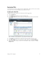
Страница 17: ...e select the Storage Center 3 In the Hardware Alerts area find the hardware alert that identifies the enclosure with the failed power supply Figure 7 Hardware Alert Identifying the Enclosure with the Failed Power Supply 4 In the Hardware tab navigation pane expand the enclosure identified in the previous step 5 Select Power Supplies The status of each power supply is displayed in the Power Supplie...

Страница 18: ...ow that you are performing a repair About this task You can replace power supply units one at a time without shutting down the expansion enclosure Steps 1 Press the power switch to turn off the PSU 2 Remove the power cable from the securing clip and disconnect the power cable from the PSU 3 Push the release tab on the PSU to the right and slide it out of the chassis using the handle CAUTION The PS...

Страница 19: ... it is fully seated and the release tab clicks into place 5 Connect the power cable to the power supply unit and make sure the cable is plugged into a power outlet 6 Secure the power cable using the clip Figure 10 Securing the Power Cable 7 Press the power switch to turn on the PSU Replacing SC180 Components 19 ...

Страница 20: ...les continue to cool the expansion enclosure NOTE When a cooling fan module fails the fan speed in the remaining modules increases significantly to provide adequate cooling The fan speed decreases gradually when a new cooling fan module is installed Identifying the Failed Cooling Fan Module To determine which cooling fan module failed use the Dell Storage Client 1 Click the Hardware tab 2 In the H...

Страница 21: ... 1 Use SupportAssist to send diagnostic data to Dell Technical Support Services 2 Contact Dell Technical Support Services to let them know that you are performing a repair About this task You can replace cooling fan modules one at a time without shutting down the expansion enclosure Steps 1 Press the release tab and pull the fan module out of the chassis using the handle CAUTION The fan modules ar...

Страница 22: ...d determine its status When functioning properly the fan module s Module OK LED turns green and the Battery fault and Fan fault LEDs are off In addition the cooling fan status indicator turns green in the Dell Storage Client 4 In the Dell Storage Client make sure that the replacement fan module is recognized and shown as up and running Next steps 1 Use SupportAssist to send diagnostic data to Dell...

Страница 23: ...n enclosure and YY is the drive position inside the expansion enclosure Figure 14 Hard Drive Drawers and Numbering 1 Bottom drawer 2 Top drawer Identifying the Failed Hard Drive To determine which hard drive failed use the Dell Storage Client 1 Click the Hardware tab 2 In the Hardware tab navigation pane select the Storage Center 3 In the Hardware Alerts area find the hardware alert that identifie...

Страница 24: ...task Hard drives can be replaced one at a time without shutting down the expansion enclosure Steps 1 Find the SC180 and drawer containing the failed drive The drawer fault LED will be lit CAUTION Before opening a drawer ensure that the Dell Storage Client does not display a temperature warning This issue needs to be rectified first to avoid potential drive failure and data loss 2 Push and hold bot...

Страница 25: ...ive drawers open the enclosure can overheat causing potential drive failure and data loss Such use may invalidate the warranty 3 Find the failed DDIC by the lit LED 4 Press the release button to unlatch the DDIC 5 Wait about ten 10 seconds for the drive to spin down 6 Slide the DDIC up and out until it is free of the DDIC slot Replacing SC180 Components 25 ...

Страница 26: ...DDIC fails to latch do not use it and request a replacement If a faulty DDIC unlatches within a closed drawer it can make the drawer unable to be opened CAUTION To maintain proper airflow the drawers must be populated with drives in whole rows at a time there are three rows of 14 drives per drawer The minimum number of drives in an enclosure is 28 one full front row in the top drawer and one full ...

Страница 27: ...g properly the hard drive indicator turns green in the Dell Storage Client and the LED on the DDIC is off Next steps 1 Use SupportAssist to send diagnostic data to Dell Technical Support Services 2 Contact Dell Technical Support Services to let them know that you have completed a repair Replacing an Enclosure Management Module The SC180 expansion enclosures support redundant hot swappable Enclosur...

Страница 28: ...nd the hardware alert that identifies the enclosure with the failed EMM IO Module Figure 19 Hardware Alert Identifying the Enclosure with the Failed EMM 4 In the Hardware tab navigation pane expand the enclosure identified in the previous step 5 Select I O Modules The status of each EMM is displayed in the I O Modules tab 6 Select the failed EMM to the display its location in the I O Module View t...

Страница 29: ...pport Services About this task EMMs can be replaced one at a time without shutting down the storage system Steps 1 Disconnect the SAS cables connected to the EMM NOTE Make sure all of the cables are labeled before disconnecting them from the EMM 2 Push the release tab to the right and pull the release lever away from the chassis 3 Grasp the release lever and pull the EMM away from the chassis Repl...

Страница 30: ...ck rails are used to install the SC180 expansion enclosure into a rack Prerequisites 1 Use SupportAssist to send diagnostic data to Dell Technical Support Services 2 Contact Dell Technical Support Services to let them know that you are replacing the rack rails 3 Shut down the expansion enclosure and expansion enclosure About this task NOTE Replacing rack rails must be performed during a scheduled ...

Страница 31: ...and Expansion Enclosure If the storage system and expansion enclosure were previously shut down perform this procedure to start them up 1 Plug the power cables into the PSUs of the storage system and expansion enclosure 2 Turn on the expansion enclosure by pressing the power switches on the PSUs NOTE Always turn on the expansion enclosure before turning on the storage system 3 Turn on the storage ...

Страница 32: ...rmine the status of the PSU LEDs If the PSU fault indicator is lit the PSU has failed If the Power OK LED is not lit check the power cord and power source into which the power supply is plugged Connect another device to the power source and check whether the device works Connect the power cord to a different power source Replace the power cord If the AC fault LED is lit this PSU is not supplying p...

Страница 33: ...anagement Modules EMMs 1 Check the status of the EMM using the Dell Storage Client 2 Check the pins and reseat the EMM a Remove the EMM b Verify that the pins on the backplane and the EMM are not bent If any pins are bent do not attempt to correct them instead contact Dell Technical Support Services for further instruction c Reinstall the EMM 3 Determine the status of the EMM power and fault LEDs ...

Страница 34: ...gle redundant path SAS chain An SCv2080 storage system supports one SC180 expansion enclosure Redundant Array of Independent Disks RAID Storage System SCv2080 Management RAID management using Dell Storage Client version 2015 R1 Back Plane Board Connectors 84 SAS hard drive connectors Two sets of SBB connectors Five cooling fan module connectors Two power supply connectors Back Panel Connectors per...

Страница 35: ...fault status One single color LED indicator for cable fault status Six single color LED indicators for data transfer status Disk Drive In Carrier DDIC One single color LED for drive fault status 6 Gb SAS IO module 14 one color LED status indicators four each for the three SAS ports and two for the module status Cooling module One single color LED indicator for module status One single color LED in...

Страница 36: ...es Width 48 26 cm 19 inches Depth front mounting bracket to rear surface 91 5 cm 36 inches Depth front surface to rear surface 96 cm 38 inches Full Weight maximum configuration 130 kg 287 lb Weight without drives 62 kg 137 lb Environmental NOTE For additional information about environmental measurements for specific configurations see dell com environmental_datasheets Temperature Operating 5 to 35...

Страница 37: ...ine shock 5 G 5 with a pulse duration of 10 ms 10 in operational orientations only Storage Z axis 30 g 10 ms half sine X and Y axes 20 g 10 ms half sine Altitude Operating 30 5 to 3000 m 100 to 10 000 ft NOTE Maximum 35 C up to 2134 m 7000 ft derate to 30 C for 2134 m to 3000 m 7000 ft to 10 000 ft Storage 300 m to 12 192 m 1000 ft to 40 000 ft Airborne Contaminant Level Class G2 or lower as defin...

Отзывы: